Author Archives: troll

NES Toploader AV Mod – Circuit Construction – Part 2

To jump between posts in this series, please visit the NES Mod Index.


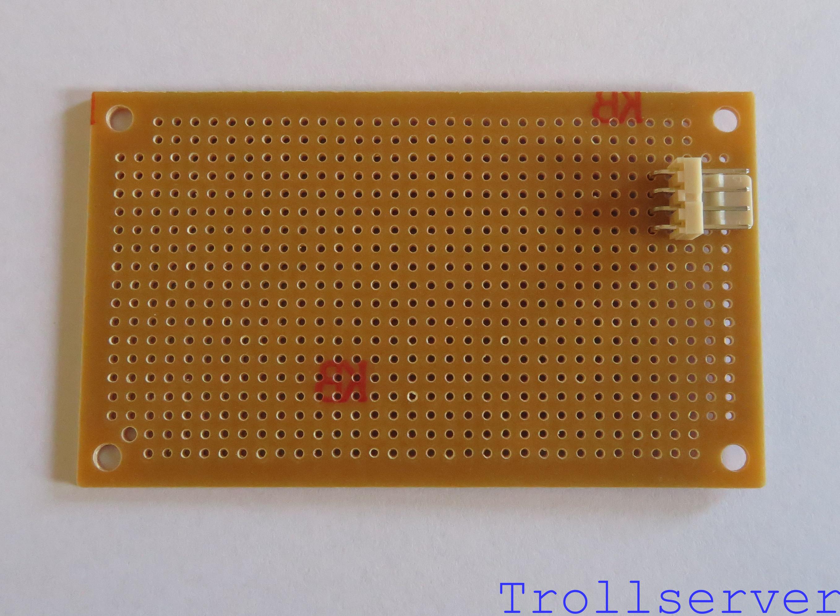
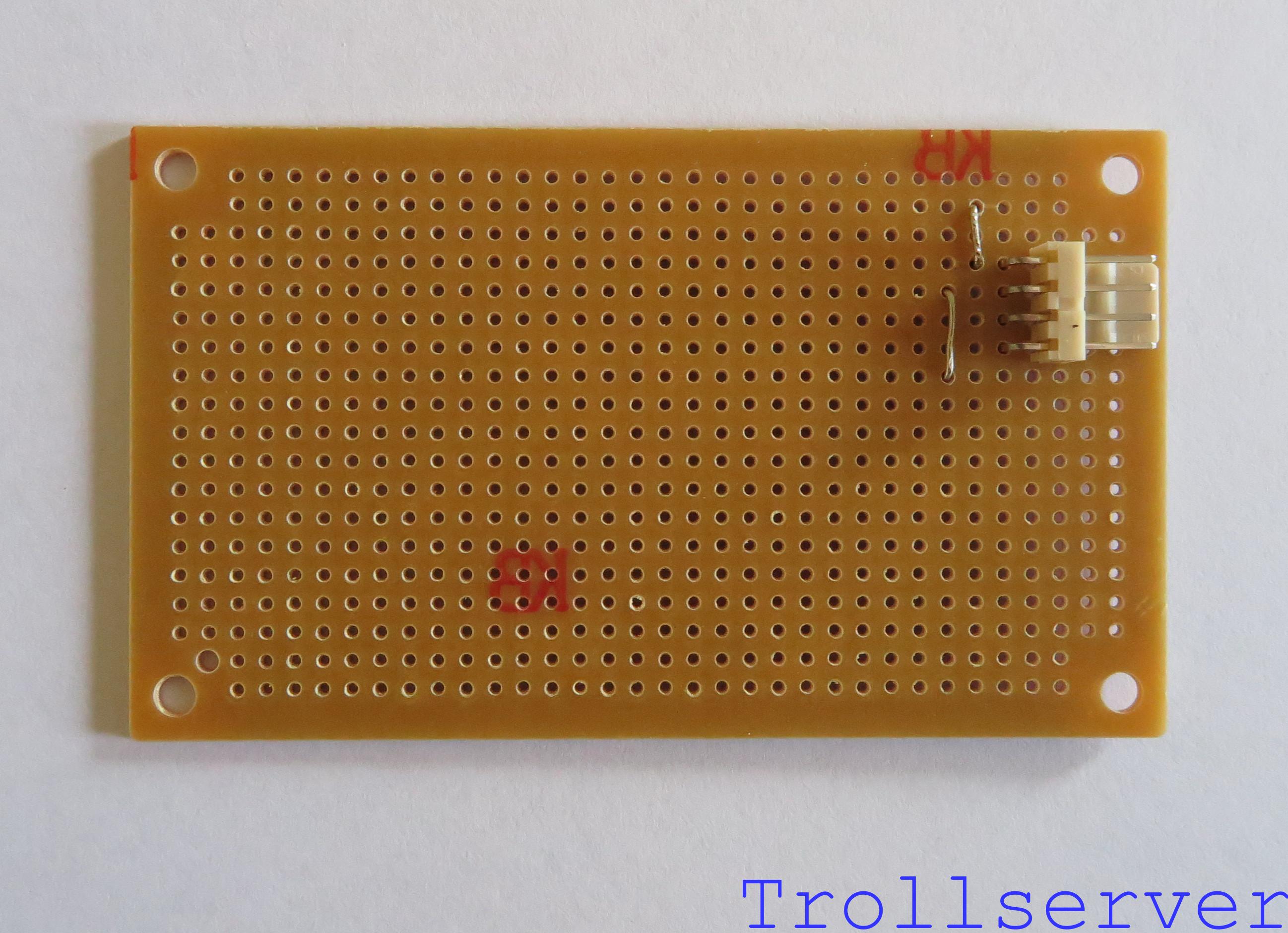
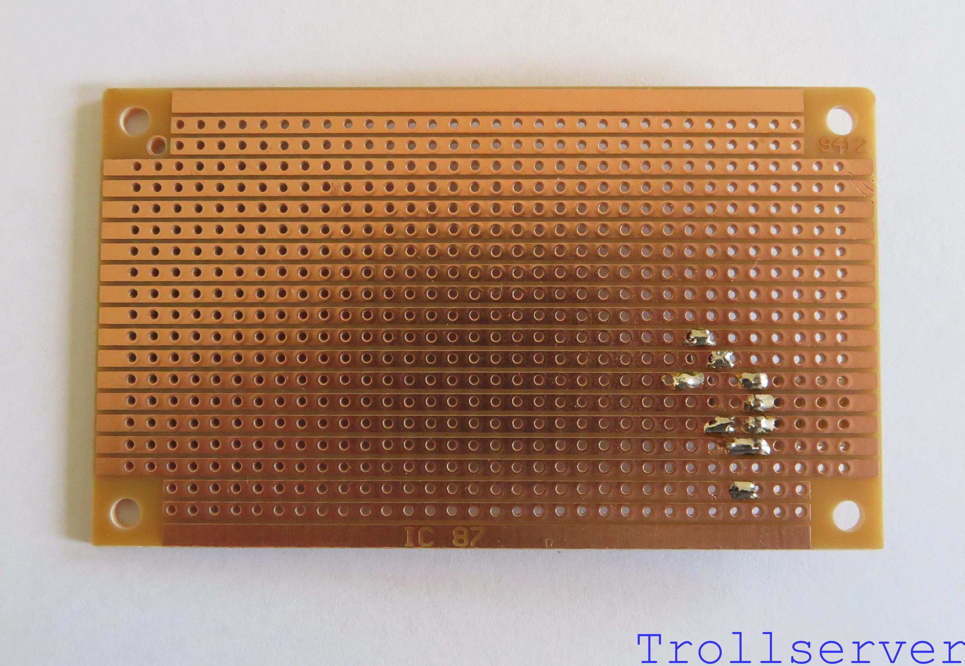
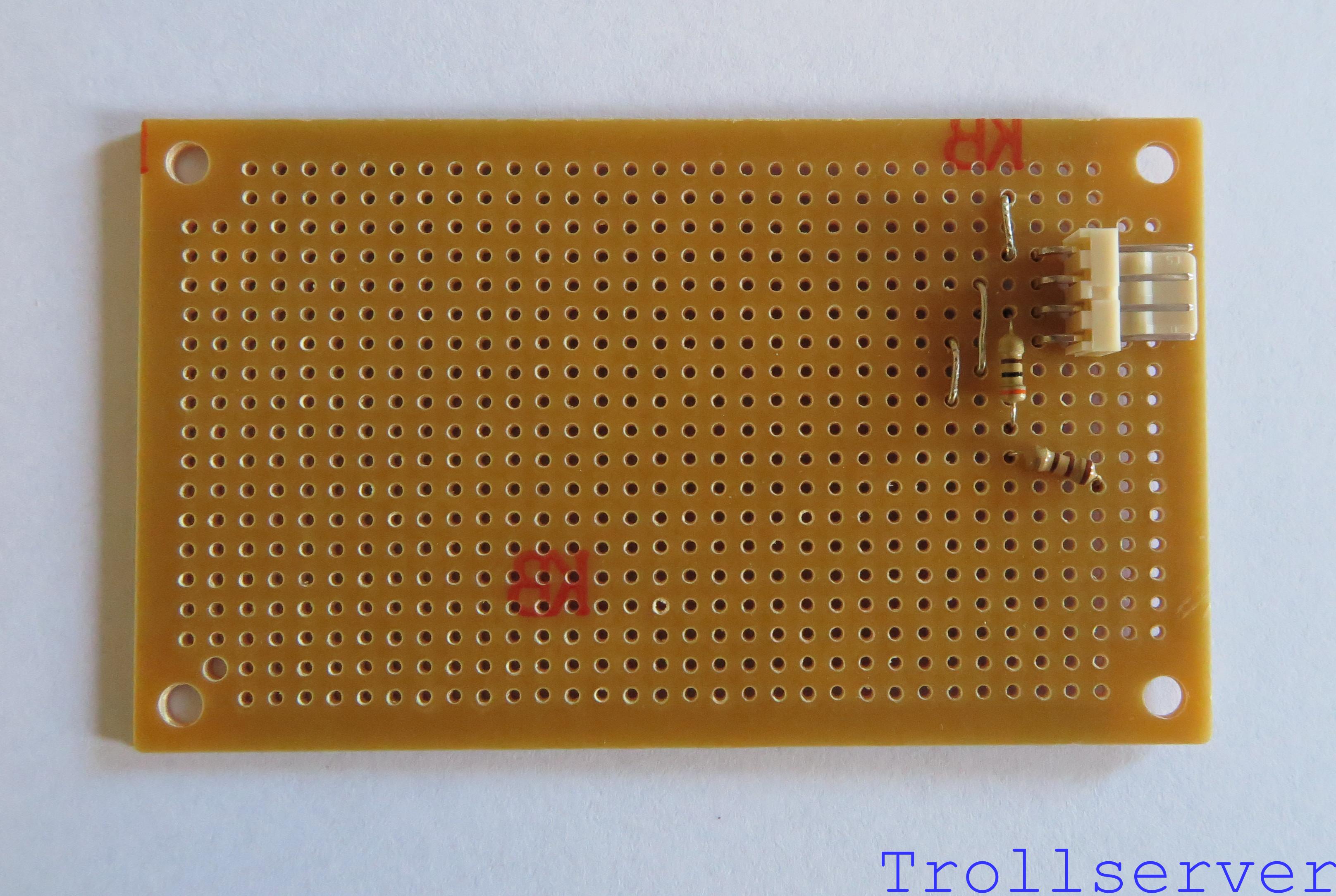
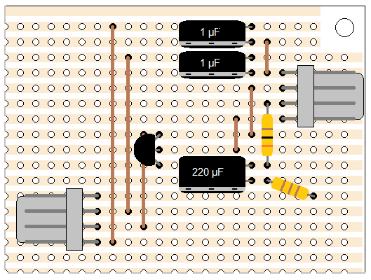
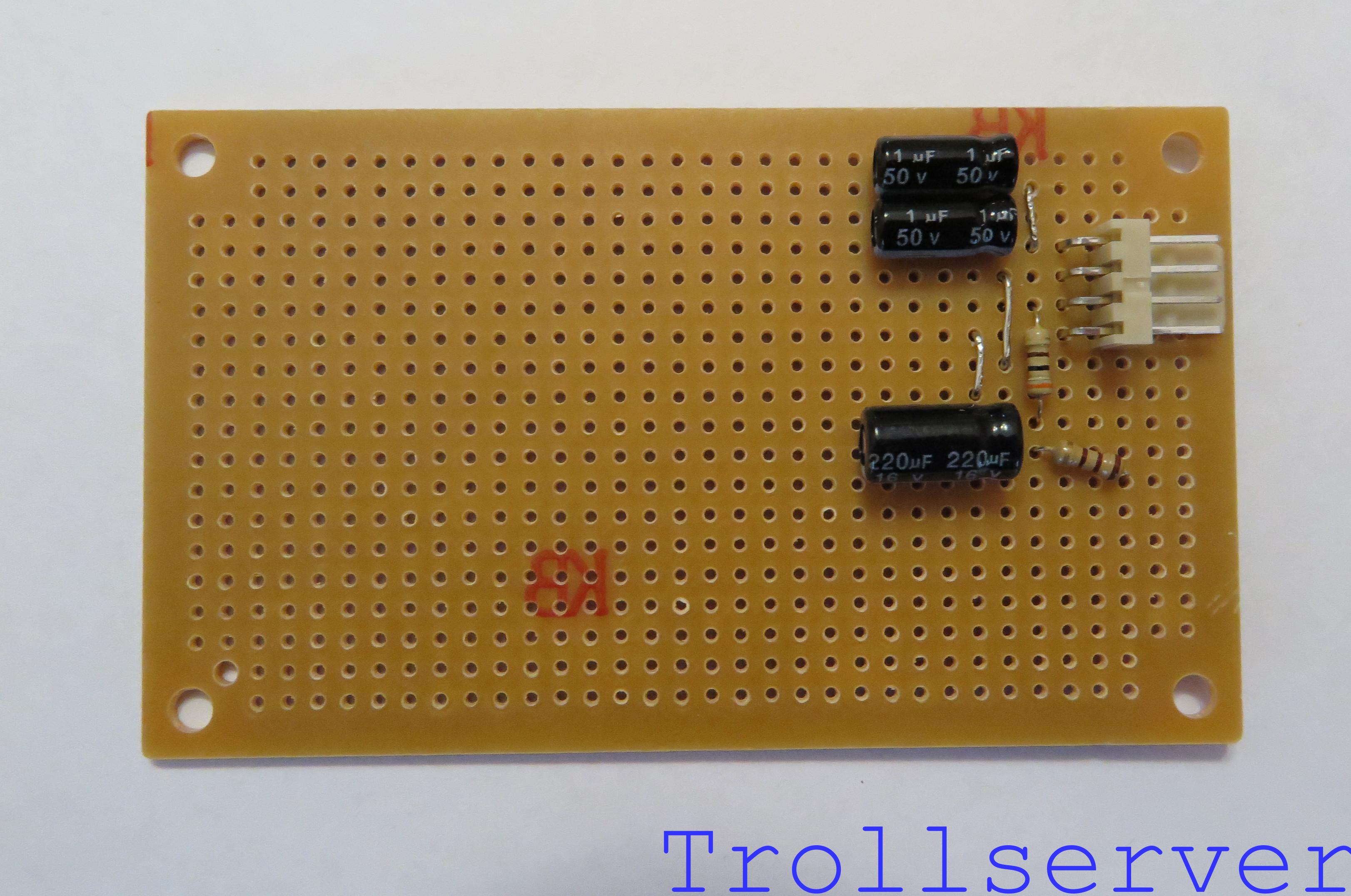
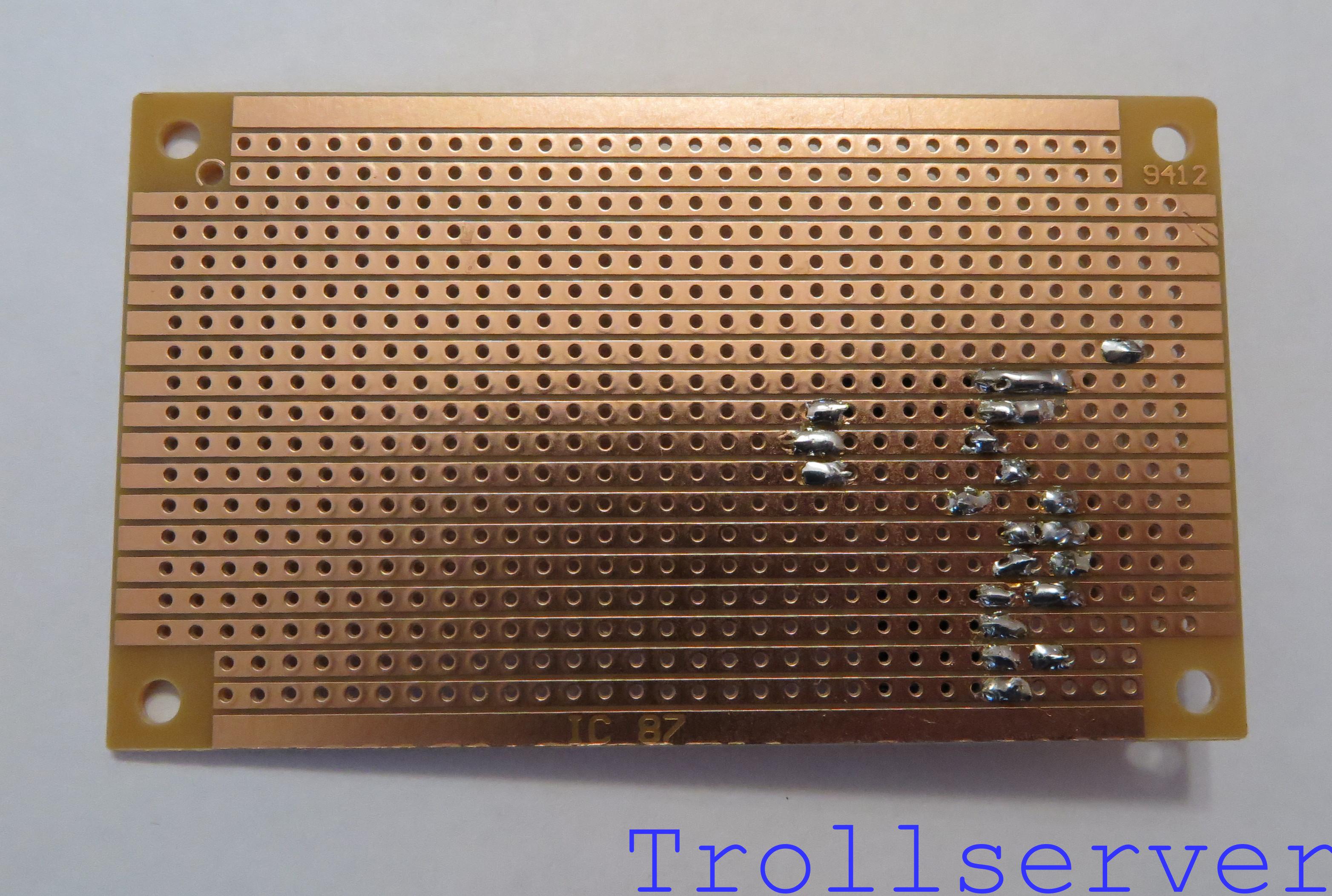
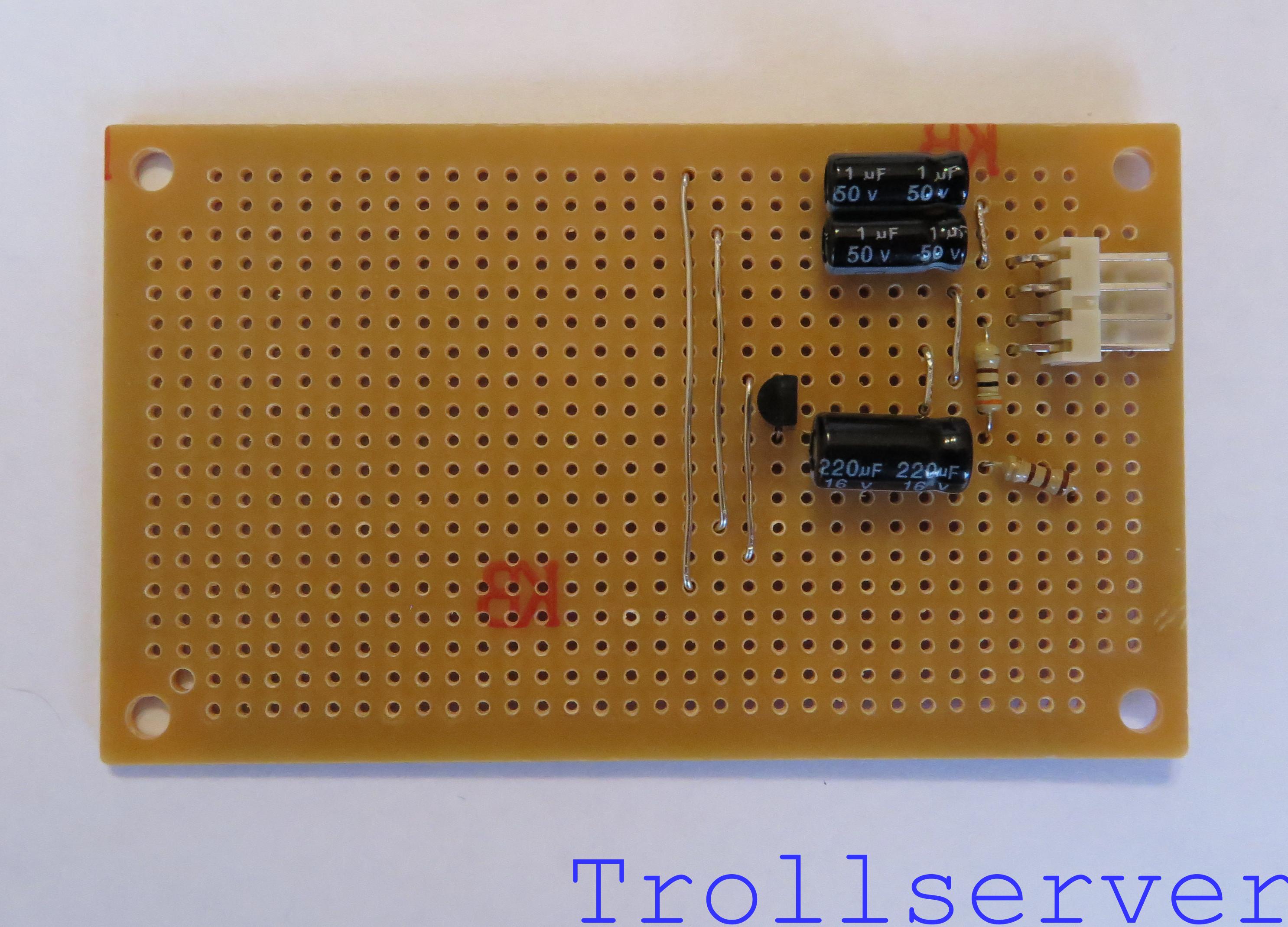
This is the second part of the instructions for building the circuit.  If your board has either too few parts or too many parts compared to the first picture on this post, you may need to go back to Part 1 to catch up or ahead to Part 3 because you have already done this step.


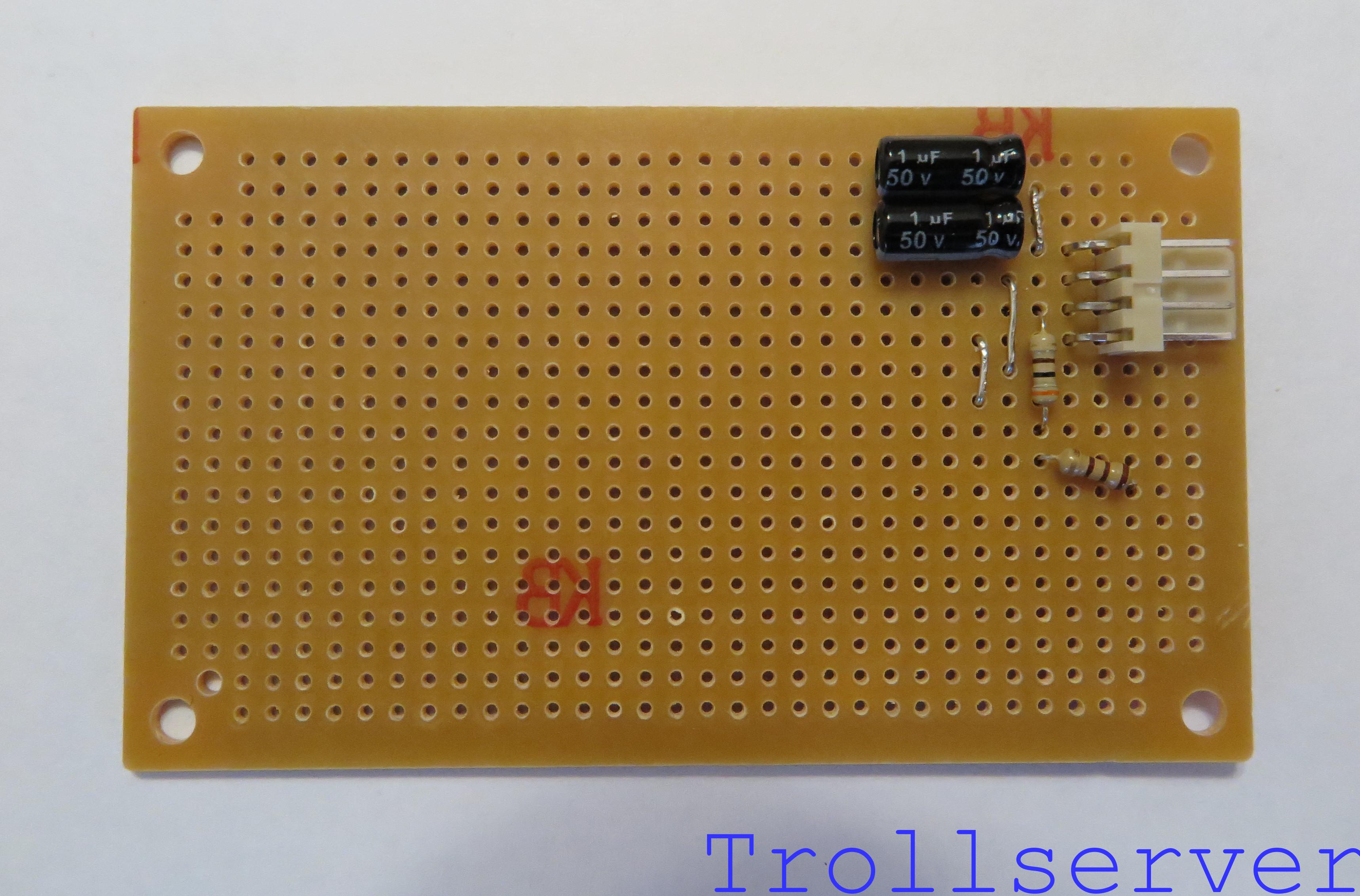
Step 7 – Audio Channel 1 Filter

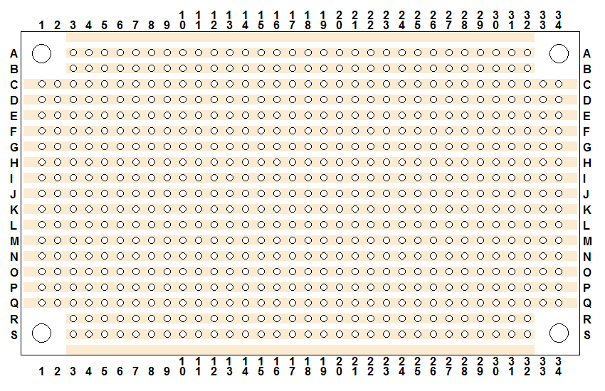
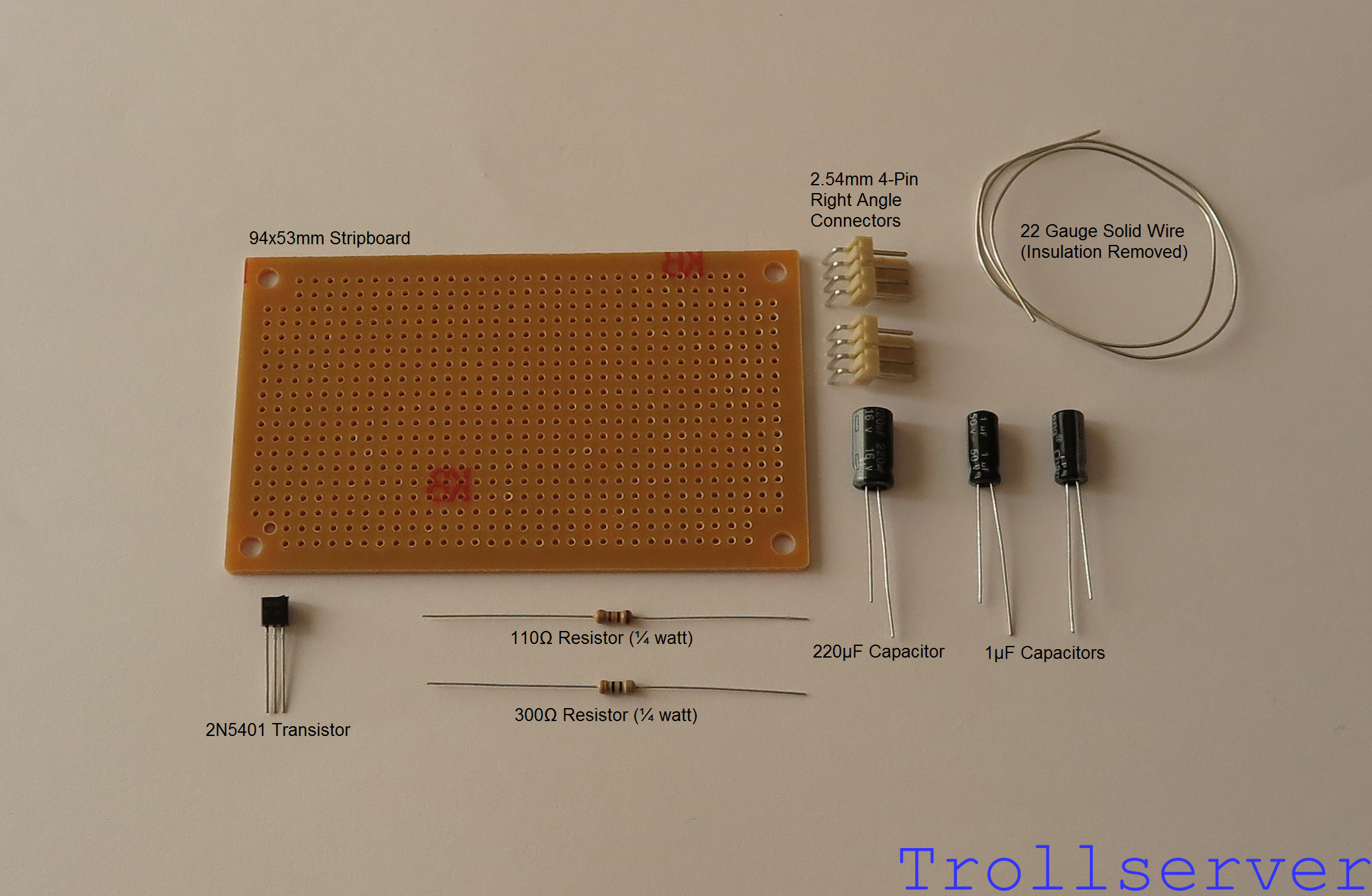
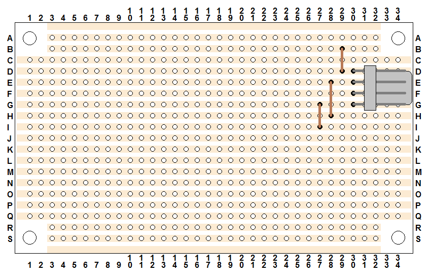
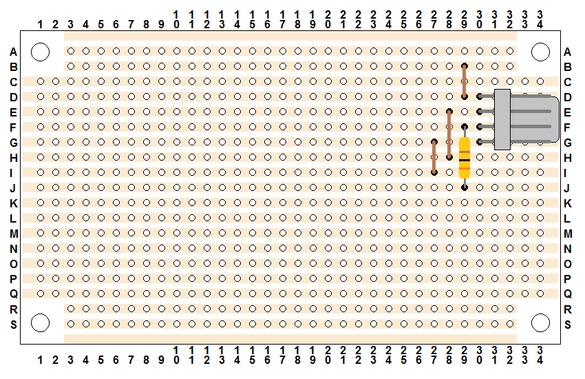
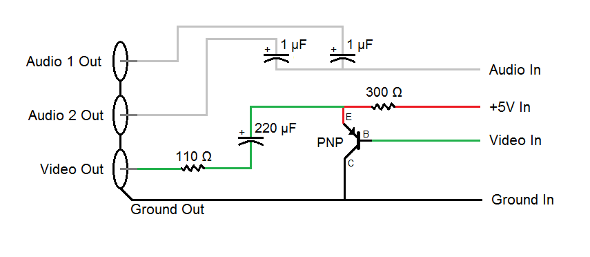
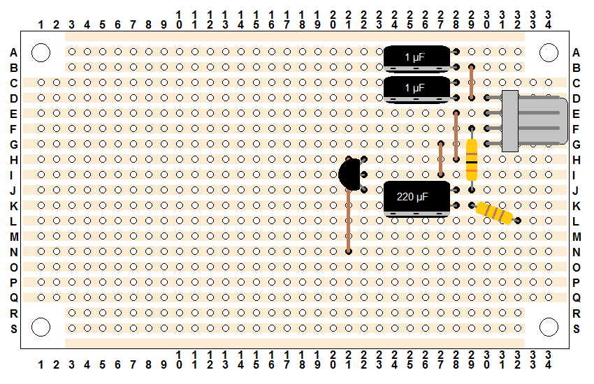
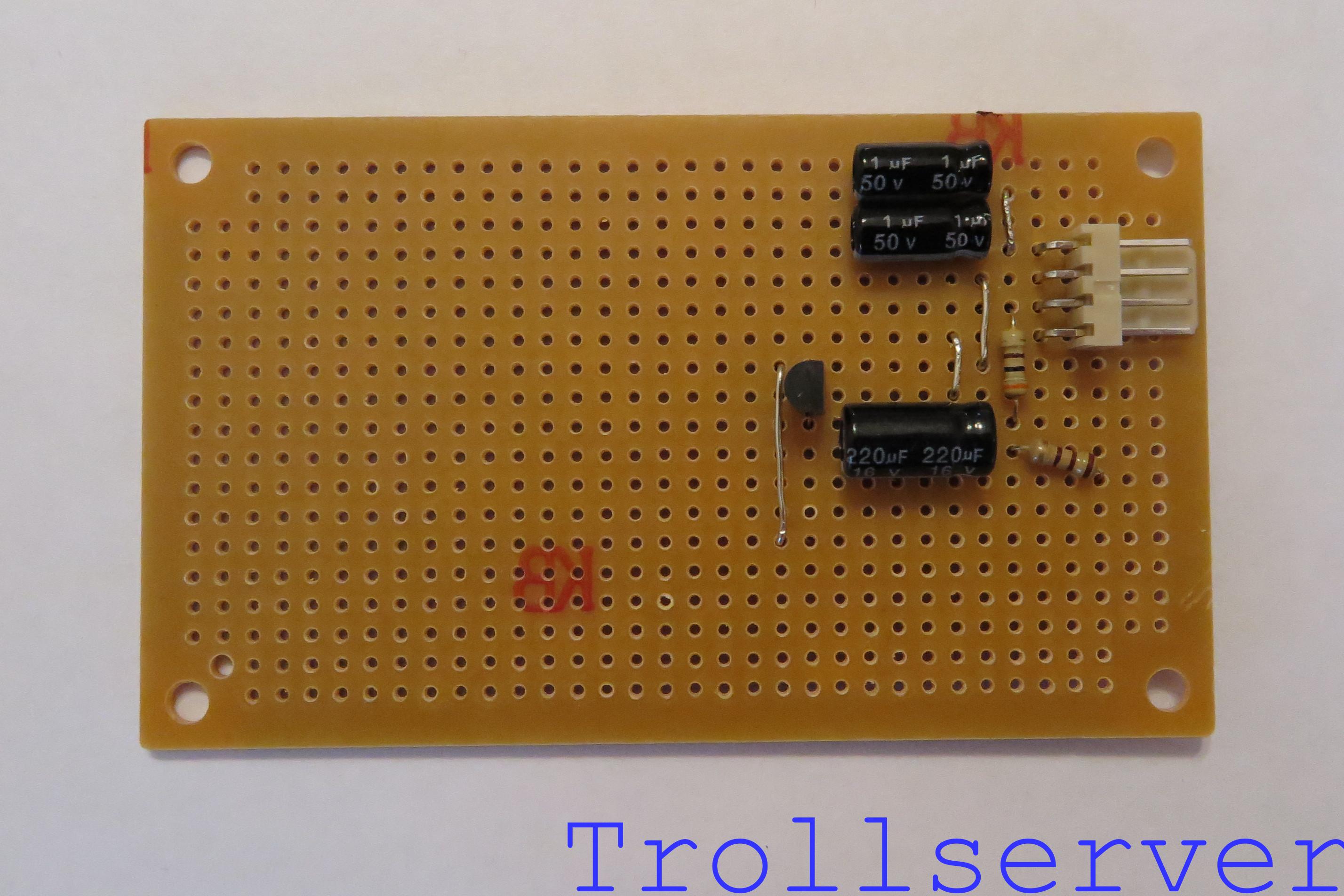
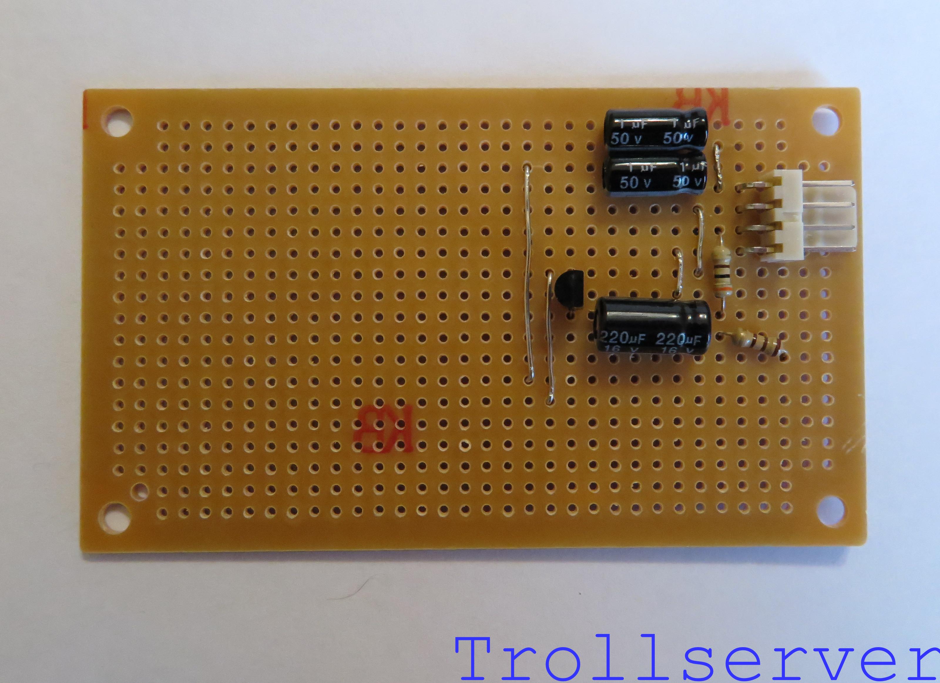
This is one of your two 1 μF electrolytic capacitors.  These guys are polarized so which way they go in is very important.  Make absolutely sure you have it facing the correct direction.  For all three of the capacitors in this circuit the negative side is toward the bottom of the board.  There will be a large and obvious band of a different color on the capacitor that has negative signs in it to indicate this.  To save space, all of the capacitors in this circuit are laying down on their sides.  This capacitor goes through holes 28-C and 28-D.

nes_av_circuit_board07

nes_av_circuit_top07

nes_av_circuit_bottom07


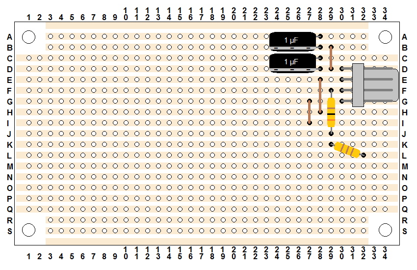
Step 8 – Audio Channel 2 Filter

This is the other one of your two 1 μF electrolytic capacitors.  Again, make absolutely sure you have it facing the correct direction.  This capacitor goes through holes 28-A and 28-B.

nes_av_circuit_board08

nes_av_circuit_top08

nes_av_circuit_bottom08


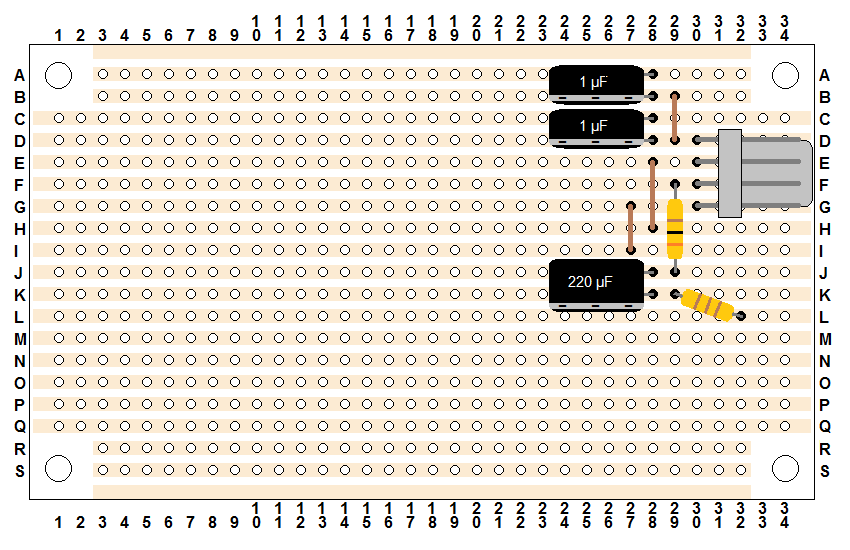
Step 9 – Video Filter

This is your 220 μF electrolytic capacitor.  It’s a lot like the 1 μF capacitors you used for filtering the audio except a bit larger.  Again, make absolutely sure you have it facing the correct direction.  (Sorry for repeating that all three times, but it’s really important.)  Similar to the two capacitors used for the audio filters, this one is also laying down on its side to save space.  This capacitor goes through holes 28-J and 28-K.

nes_av_circuit_board09

nes_av_circuit_top09

nes_av_circuit_bottom09


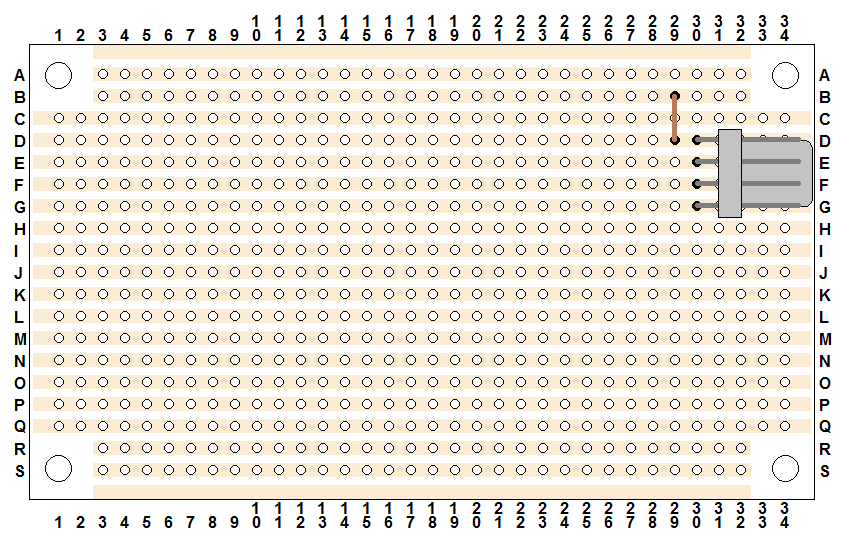
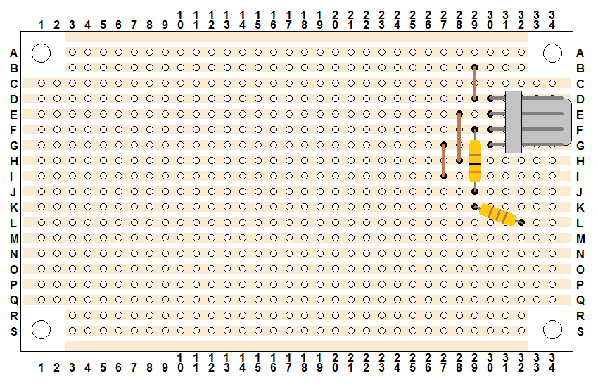
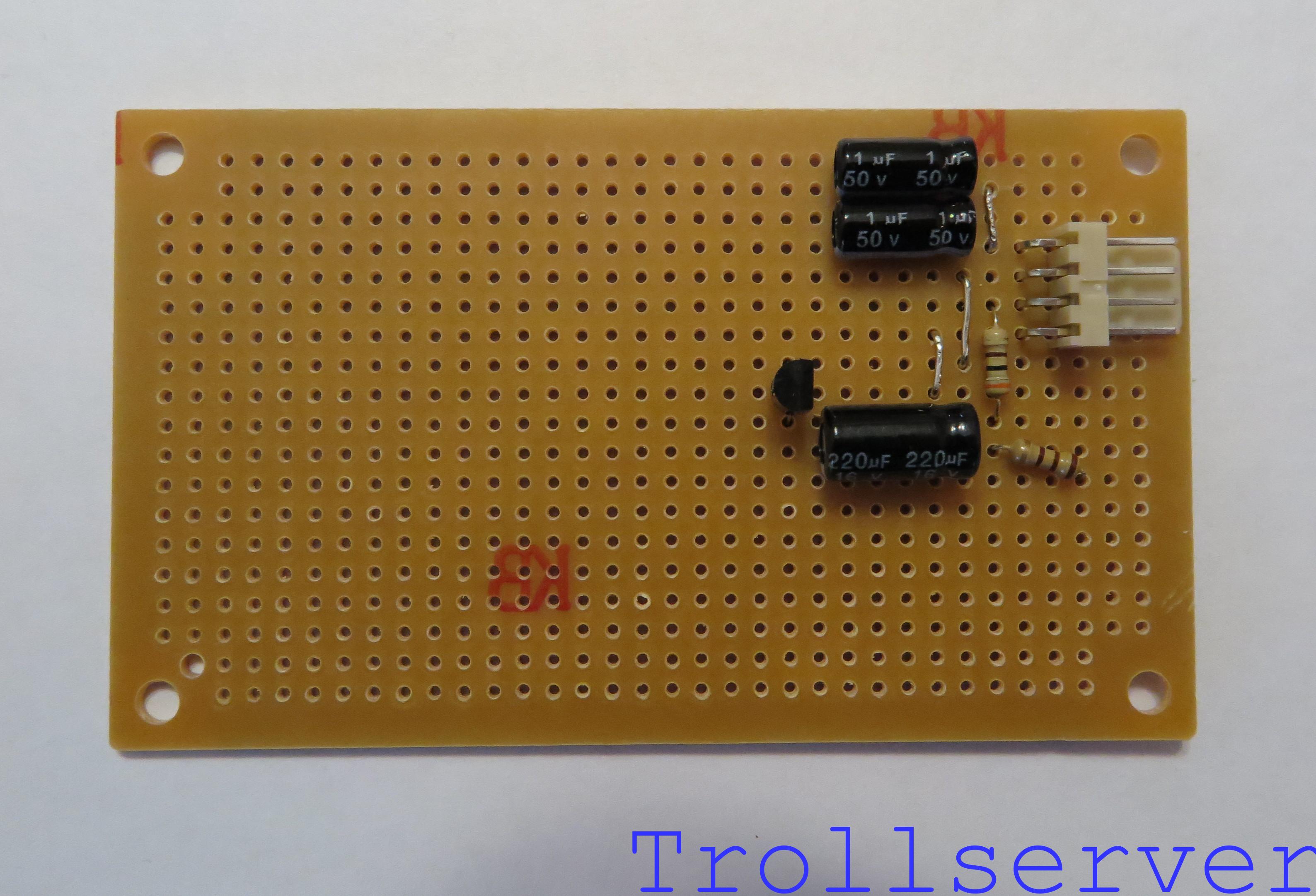
Step 10 – Video Amplifier

This little transistor is the main workhorse of this circuit.  It turns the weak video signal we get off the NES motherboard into something powerful enough to make it to your TV through multiple feet of RCA wire.  This diagram was built assuming you are using a transistor that has the pin order of Emitter – Base – Collector (when looking at the flat side, from left to right).  If this is not the case you should stop here and get one that does.  The transistor I suggested follows this pin order, but if you purchased a NES AV Mod Kit from Console5 the one they provide does not.  If you hook it all up and audio works, but there is no video, there is a very good chance that your transistor has a different pin order.

The transistor goes through the board with the flat side facing the input connector through holes 22-H, 22-I, and 22-J.  You may need to separate the pins on your transistor a little to get them through the correct holes, and when pushing it down toward the board there will be an obvious point where it doesn’t want to go any further.  Don’t push it past that point or you will likely damage it and you can’t get it flush with the stripboard anyway. nes_av_circuit_board10

nes_av_circuit_top10

nes_av_circuit_bottom10


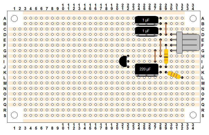
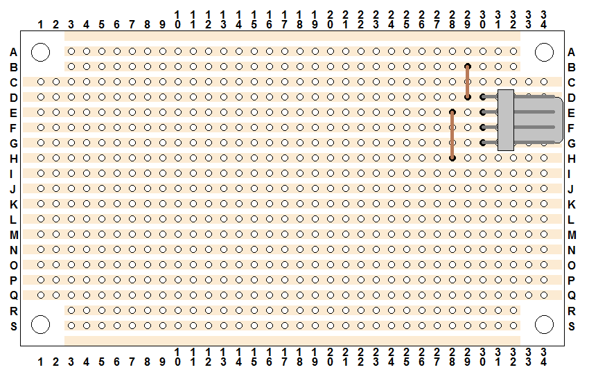
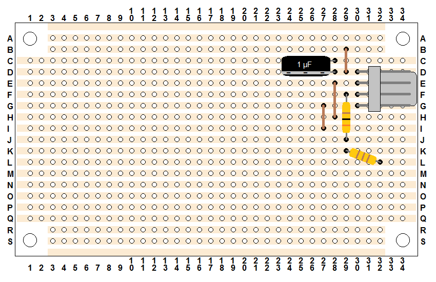
Step 11 – Output Ground

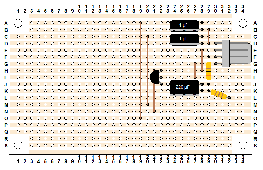
This is another piece of stripped wire.  It is used to supply ground to the output connector.  It goes through holes 21-H and 21-N.  Don’t panic, it’s not actually as close to the transistor as shown here.  I had to draw the transistor a little to one side so you could see which holes it goes through.

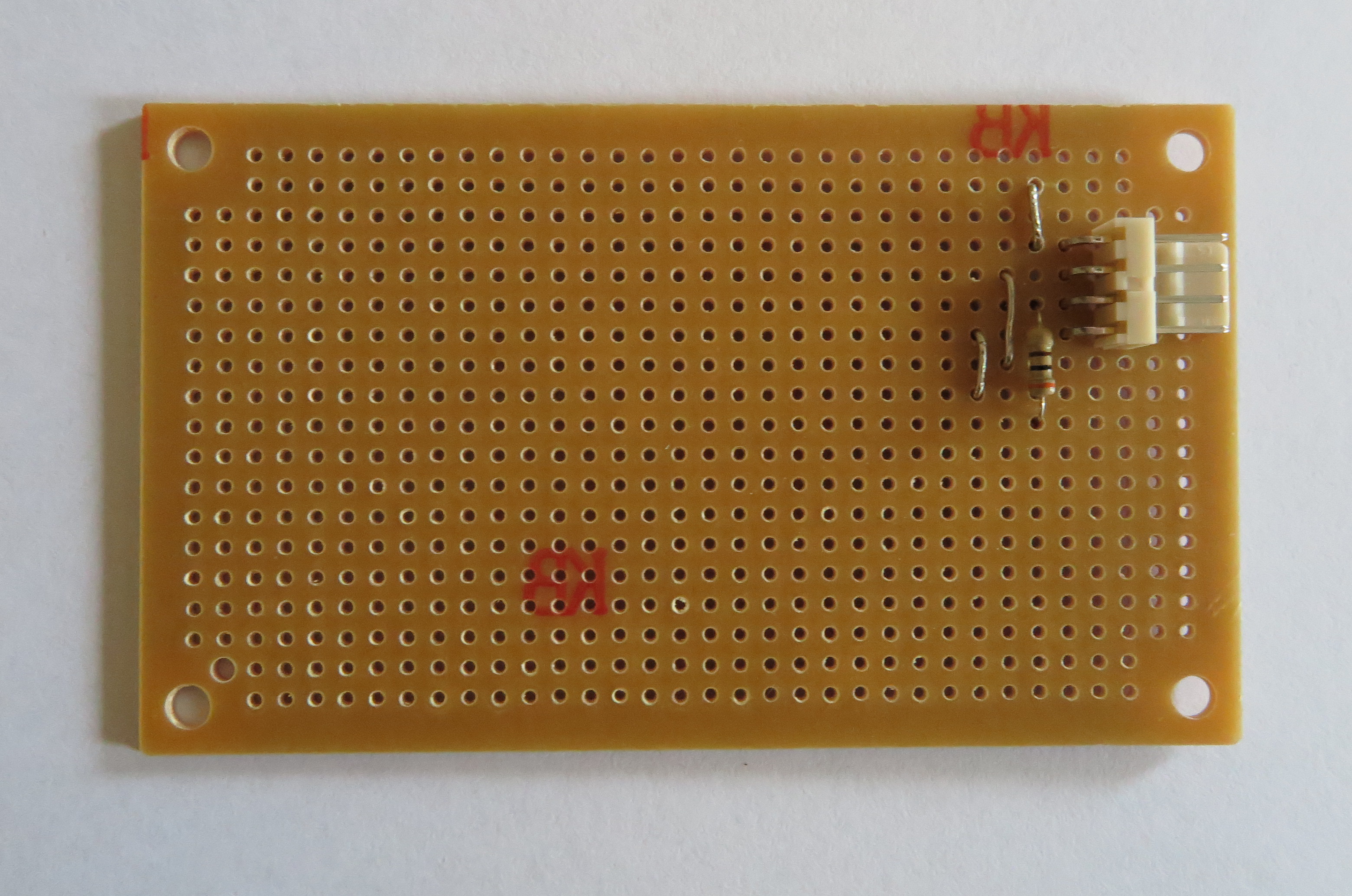
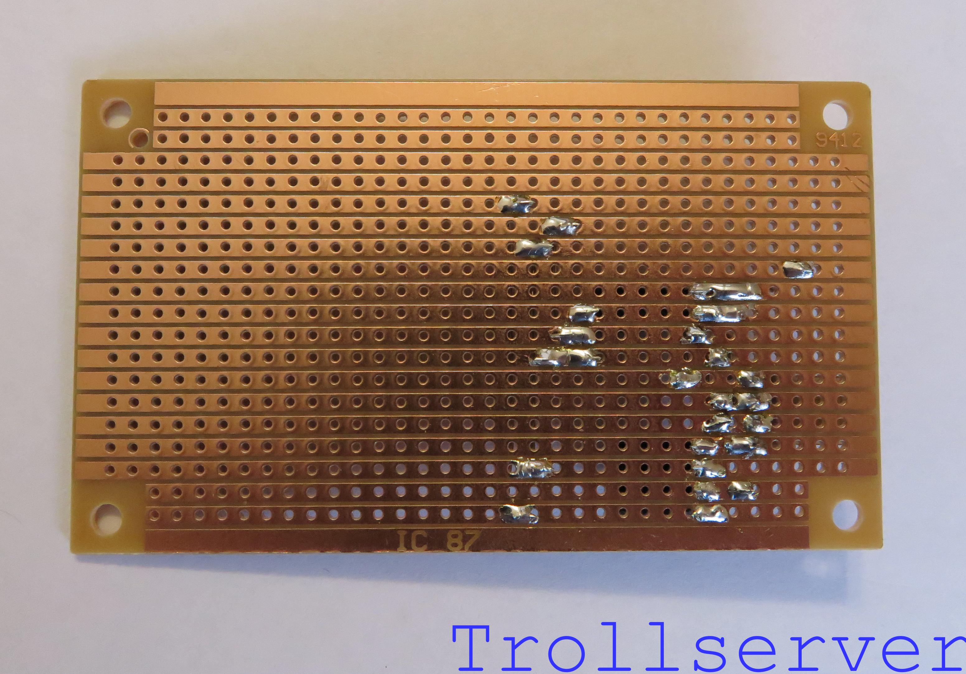
Just like the uninsulated wires used on the input side of the circuit, the next couple of steps all involve stripped wire on the front of the circuit board.  The main difference is that these are significantly longer pieces of wire.  Be sure you make the wire tight, flush to the circuit board, as close to a straight line as possible, and that none of the wires touch each other.  Since they aren’t insulated, that would obviously cause problems.

nes_av_circuit_board11

nes_av_circuit_top11

nes_av_circuit_bottom11


Step 12 – Output Audio Channel 1

This is another piece of stripped wire.  It is used to get the first channel of filtered audio to the output connector.  It goes through holes 20-C and 20-M.  Try to line the wires up with the holes on the board to assist you in keeping the wires nice and straight.nes_av_circuit_board12

nes_av_circuit_top12

nes_av_circuit_bottom12


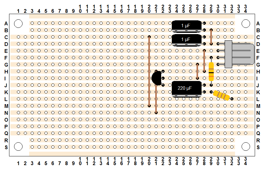
Step 13 – Output Audio Channel 2

This is another piece of stripped wire.  It is used to get the second channel of filtered audio to the output connector.  It goes through holes 19-A and 19-O.

nes_av_circuit_board13

nes_av_circuit_top13

nes_av_circuit_bottom13


Head over to Part 3 for the exciting conclusion of the circuit construction.

To jump between posts in this series, please visit the NES Mod Index.

NES Toploader AV Mod – Circuit Construction – Part 1

To jump between posts in this series, please visit the NES Mod Index.


Now it’s time to build the circuit.  This process is going to involve some careful placement of parts onto the stripboard and it’s super easy to “miss” when placing something.  To help reduce the chances of this happening, I’ve built these instructions in a way that allows you to use other parts you’ve already placed on the board as reference points for parts you are about to place.  The side effect of this approach is that I can’t break the circuit into logical areas like “the audio half” or “the video half” because I’ll be mixing and matching which part of the circuit is being worked on in any given step.

I have also created a series of diagrams, labeled them like an over-sized chess board, and tried to explain what I’m doing in each step in English as well as possible.  My best advice is that you simply go slowly and quadruple check what you are doing before you solder something in place.  Good luck and have fun!  Let’s get started…


Step 0 – A blank Stripboard.

My diagram should very closely resemble the stripboard you have in front of you if you bought the one I recommended.  I follow a couple of conventions through this process to try to make what is happening a little more obvious.  For the sake of these instructions, I define the “front” of the stripboard as the side of the board that does NOT have the copper strips on it.  The “back” is the side where you can see all the copper strips.  Even though my hand drawn diagrams show the copper strips, they are provided only for electrical reference as my diagrams all show the stripboard from the front.  You ALWAYS place parts on the front of the stripboard.  When a hole in the stripboard has something in it, I fill it in black so it’s obvious which hole was used to go through the stripboard.

Each step in this process will include an updated hand drawn diagram that shows what it should look like AFTER adding the component described in the step.  Then it will show a photo of the front of the circuit board with the new component in place.  Finally it will show the board flipped over vertically to show the back of the circuit board with the solder connections.  Note that flipping the board obviously flips the top and the bottom of the circuit visually.  That means parts added to the top of the board will be at the bottom on this view.

The process of putting a part onto the board goes like this:

  1. Put the part on the front of the stripboard.
  2. Make sure it is in exactly the correct place (and facing the correct direction).
  3. Carefully flip the stripboard over, holding the part in place.
  4. Bend the leads of the part over so they are flush with the back of the stripboard in the direction that lines them up with the strip of copper that lines up with the hole they came through.  (Some parts have very short leads, bending them is not required.)
  5. Solder the part in place.
  6. Trim the leads of the part to as short as you can without messing up the solder.  (Don’t bother trimming leads on parts with very short leads.)

nes_av_circuit_board00

Here are all of the parts you’ll need to build the circuit board, shown in one picture with convenient labels.

circuit_parts


Step 1 – Input Connector

The first part to place on the board is the input connector.  This is where the power, ground, audio, and video enter your circuit board from the NES motherboard.  It has 4 leads that should be placed in 30-D, 30-E, 30-F, and 30-G.  This component is placed where it is because we will need a little bit of room above the input connector for the audio half of the circuit and we are trying to support the entire plastic base of the connector with the stripboard.

nes_av_circuit_board01

nes_av_circuit_top01

nes_av_circuit_bottom01


Step 2 – Audio Splitter

This “part” is actually just a piece of solid wire that has had the insulation taken off.  You’ll need several of these as you build this board, so you can strip a reasonable length of wire now while you are working on this step.  Don’t bother cutting it into short pieces either, it’s much easier to work with as a longer wire when you are weaving it in and out of the stripboard and you will be trimming the extra off after soldering it anyway.  This wire goes down through holes 29-B and 29-D and serves the purpose of splitting the audio input into 2 “channels”.

The next couple of steps all involve stripped wire on the front of the circuit board.  Be sure you make the wire tight and flush to the circuit board and that none of the wires touch each other.  Since they aren’t insulated, that would obviously cause problems.

nes_av_circuit_board02

nes_av_circuit_top02

nes_av_circuit_bottom02


Step 3 – Transistor Ground

This is another piece of stripped copper wire.  This time the wire goes through holes 28-E and 28-H and serves the purpose of providing ground to the transistor (which won’t be placed on the board for a while).  Note that this is one column over to the left of the previous wire.  Don’t put it directly below the other piece of wire because we need that space later.

nes_av_circuit_board03

nes_av_circuit_top03

nes_av_circuit_bottom03


Step 4 – Transistor Video Signal 

This is another piece of stripped copper wire.  This time the wire goes through holes 27-G and 27-I and serves the purpose of getting our weak input video signal to the transistor for amplification.

nes_av_circuit_board04

nes_av_circuit_top04

nes_av_circuit_bottom04


Step 5 – Transistor Power Resistor

This is the 300 Ω resistor (orange – black – brown – gold) and conveys the +5 volt input power to the transistor so the weak video signal can be amplified.  I find it’s usually easier to work with resistor placement if you pre-bend the leads to 90 degrees.  This gets them pointing in a direction that makes lining them up with the correct holes in the stripboard much easier.  The resistor leads go through holes 29-F and 29-J.

nes_av_circuit_board05

nes_av_circuit_top05

nes_av_circuit_bottom05


Step 6 – Video Output Resistor

This time we’ll be using the 110 Ω resistor (brown – brown – brown – gold).  Its purpose is to take the amplified and filtered video signal to the output connector for transmission to the TV.  This resistor is crooked to save space and special care should be used to make sure you have it in the correct holes.  It goes through holes 29-K and 32-L.  This starts directly below the other resistor and the other side is only one row further down the board.

nes_av_circuit_board06

nes_av_circuit_top06

nes_av_circuit_bottom06


Head over to Part 2 to continue.

To jump between posts in this series, please visit the NES Mod Index.

NES Toploader AV Mod – Circuit Design

To jump between posts in this series, please visit the NES Mod Index.


This post can probably be skipped by a lot of people.  Electronics nerds such as myself may like to know exactly what they’re building and why.  If you are curious or interested in the nerdier bits of this process then you should stick around.  If not, continue to the next post about how to actually build this circuit.  I won’t judge you.  🙂

For reasons I can’t properly explain, it seems like every AV Mod I’ve ever done has enough power on the audio signal to go right to the TV but the video signal needs to be amplified first.

In an attempt to make every output signal as clean as possible we pass both the audio and video through capacitors as a way of filtering out any rogue direct current (DC) that may have made its way into the signals.  The result is potentially cleaner audio and video.

This diagram represents both the audio and the video parts of the circuit together.  The circles on the left side of the diagram represent the three RCA jacks that will be on the back of the NES when we are done.

nes_av_circuit

As you can see there, we have a transistor taking in the video signal from the NES and amplifying it with +5V before sending it on its way to the TV but the audio wanders through some capacitors for filtering and heads right out.

To redesign this circuit into a stripboard configuration is relatively straightforward.  There are only a few tricky parts to keep in mind.  The fact that I’d like to keep my wires color coded so they make sense and the 4-connector wire I like to use has the wires in a specific color order means a couple of constraints on how the input and output work.  Specifically, the 4-connector wire is all stuck together in the following color order:  White, Black, Red, Green.  I like to at least try to use the wires in a way that makes sense with either standard DC current (red is positive and black is negative) or with the standard colors used in RCA jacks for composite audio and video (yellow is video, white and red are audio).  Obviously that’s too many colors for 4-connector wire, and we don’t have all the right colors.  Here is how I line everything up to make it make as much sense as possible:

Input (top to bottom)

  • White = Audio (based on composite standard)
  • Black = Ground (based on DC standard)
  • Red = +5 Volts (based on DC standard)
  • Green = Video (similar to composite standard, but we don’t have yellow so we use green)

Output (top to bottom)

  • Green = Video (same color as input)
  • Red = Audio (based on composite standard)
  • Black = Ground (same color as input)
  • White = Audio (based on composite standard)

You’ll notice that the input and output are actually a little different.  I don’t mean how I use the 4-connector wire backwards for the output, I mean what things are coming out of the circuit.  Specifically we have +5 volts going into the circuit but not coming out.  That’s because it is only used for amplifying the video signal and we don’t need it anywhere else.

The 4-pin connectors I use to make this circuit nice and modular mean that all 4 inputs or outputs are next to each other on the board.  Finally, I prefer not having to cut stripboard conductors if I don’t absolutely have to.  All these rules I’ll be following mean that the final board will be slightly larger than it absolutely has to be, some of the components will need to be shifted around a little to make them convenient, and there will be a couple of extra wires on the board to get connections where I need them.

This is what the final design of the stripboard looks like.  (Don’t panic, I break down the construction of this circuit board into 3 blog posts with dozens of simple steps to follow.)

stripboard_circuit_no_labels

Note:  If you plan to do an NES Overclock Mod too, I recommend you construct the super compact version of this board.  It’s a bit more complicated to build, has completely different input and output wire order, and it throws almost all of the rules mentioned above out the window for the sake of saving a bit of space.  The advantage is that in a crowded NES the smaller board helps things fit in better and the compact board is 8 holes tall instead of 16, and 20 holes wide instead of 22.  Every little bit counts when things get crowded.


To jump between posts in this series, please visit the NES Mod Index.

1 2 3 4 5 6 20