NES Toploader AV Mod – Circuit Construction – Part 2
To jump between posts in this series, please visit the NES Mod Index.
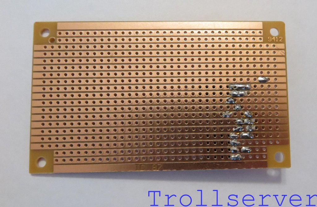
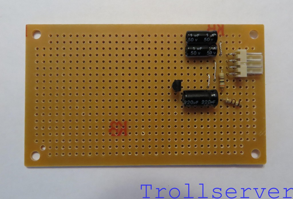
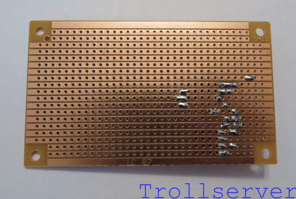
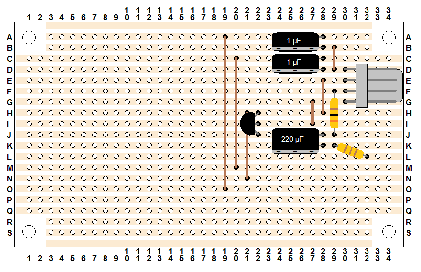
This is the second part of the instructions for building the circuit. If your board has either too few parts or too many parts compared to the first picture on this post, you may need to go back to Part 1 to catch up or ahead to Part 3 because you have already done this step.
Step 7 – Audio Channel 1 Filter
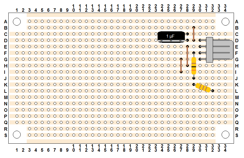
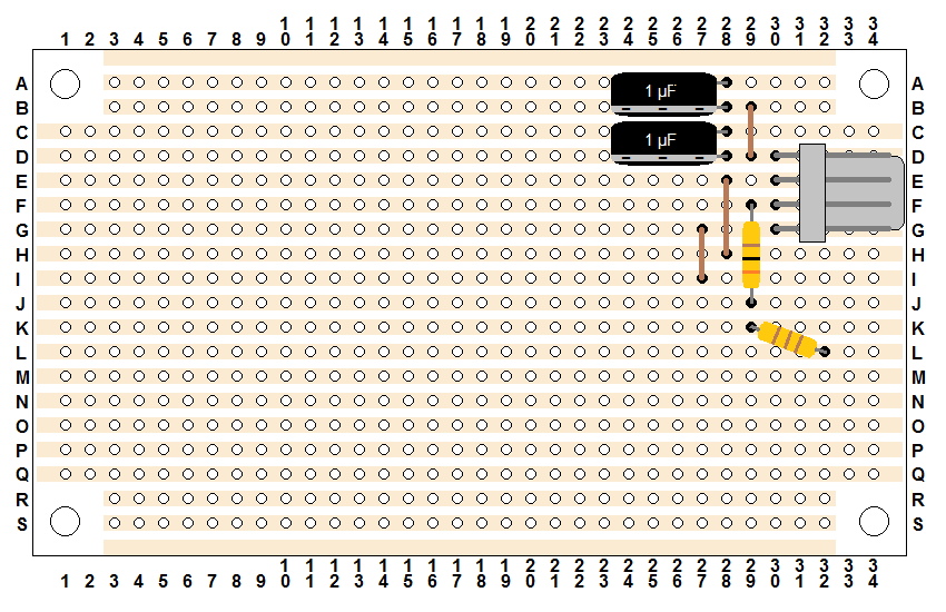
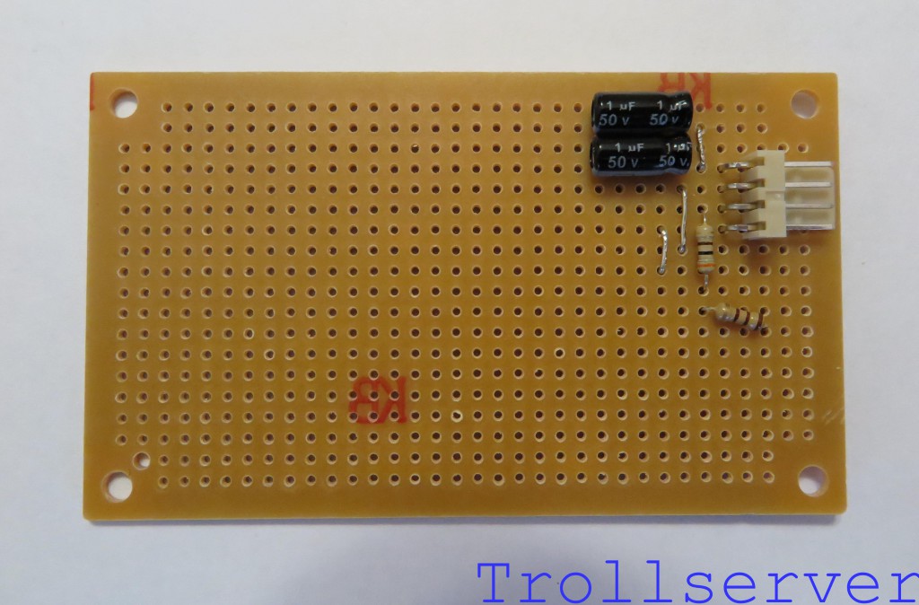
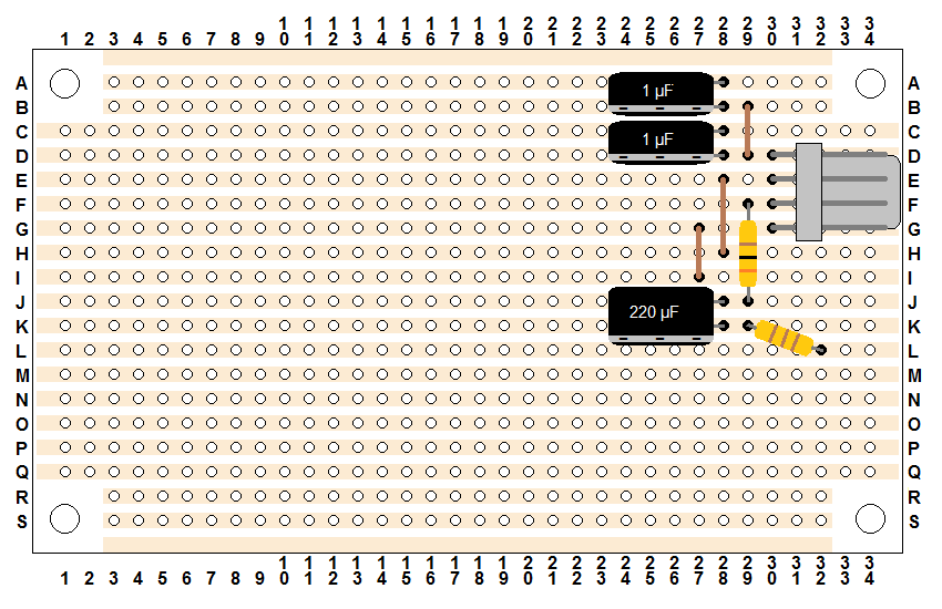
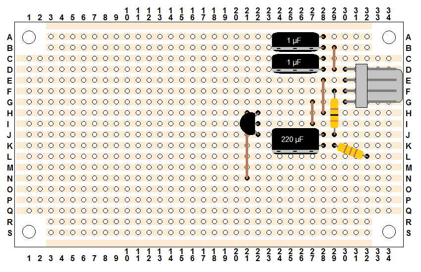
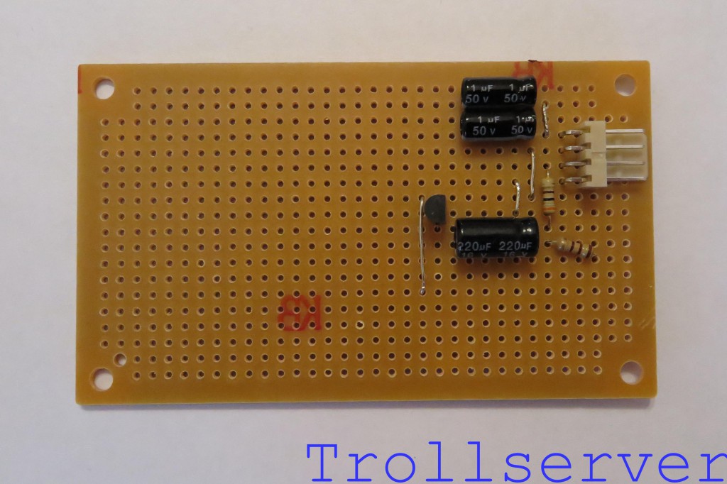
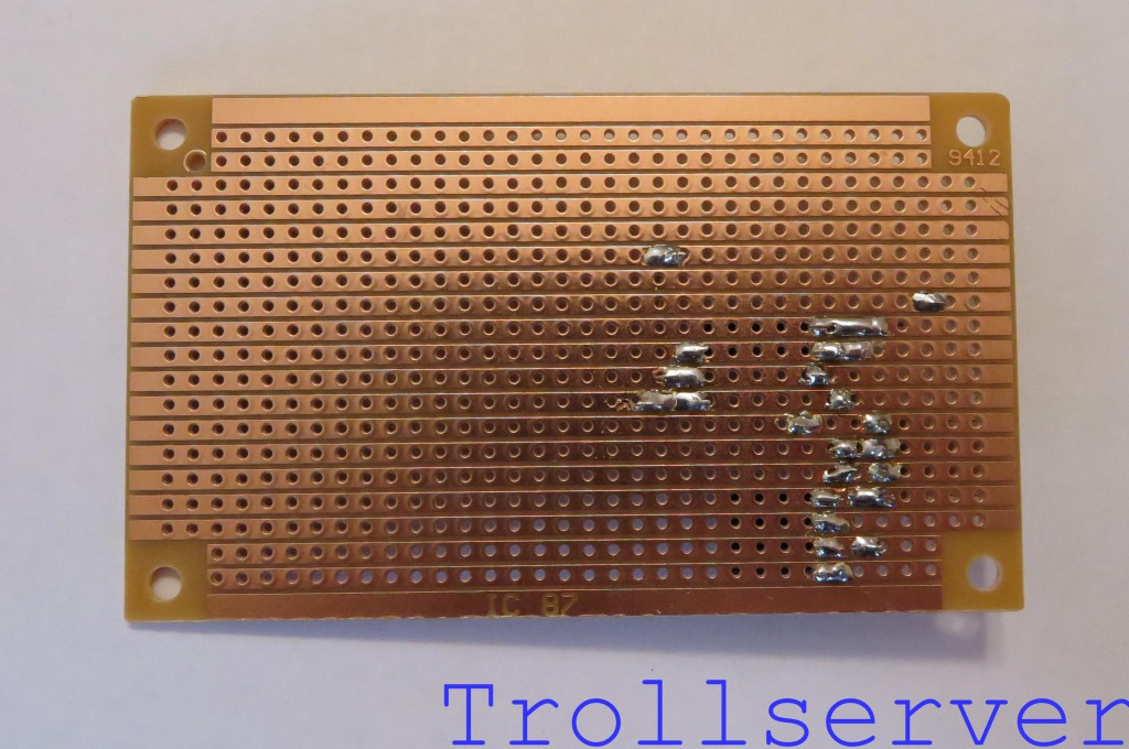
This is one of your two 1 μF electrolytic capacitors. These guys are polarized so which way they go in is very important. Make absolutely sure you have it facing the correct direction. For all three of the capacitors in this circuit the negative side is toward the bottom of the board. There will be a large and obvious band of a different color on the capacitor that has negative signs in it to indicate this. To save space, all of the capacitors in this circuit are laying down on their sides. This capacitor goes through holes 28-C and 28-D.
Step 8 – Audio Channel 2 Filter
This is the other one of your two 1 μF electrolytic capacitors. Again, make absolutely sure you have it facing the correct direction. This capacitor goes through holes 28-A and 28-B.
Step 9 – Video Filter
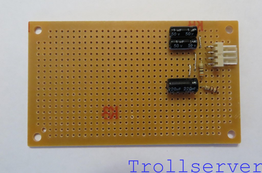
This is your 220 μF electrolytic capacitor. It’s a lot like the 1 μF capacitors you used for filtering the audio except a bit larger. Again, make absolutely sure you have it facing the correct direction. (Sorry for repeating that all three times, but it’s really important.) Similar to the two capacitors used for the audio filters, this one is also laying down on its side to save space. This capacitor goes through holes 28-J and 28-K.
Step 10 – Video Amplifier
This little transistor is the main workhorse of this circuit. It turns the weak video signal we get off the NES motherboard into something powerful enough to make it to your TV through multiple feet of RCA wire. This diagram was built assuming you are using a transistor that has the pin order of Emitter – Base – Collector (when looking at the flat side, from left to right). If this is not the case you should stop here and get one that does. The transistor I suggested follows this pin order, but if you purchased a NES AV Mod Kit from Console5 the one they provide does not. If you hook it all up and audio works, but there is no video, there is a very good chance that your transistor has a different pin order.
The transistor goes through the board with the flat side facing the input connector through holes 22-H, 22-I, and 22-J. You may need to separate the pins on your transistor a little to get them through the correct holes, and when pushing it down toward the board there will be an obvious point where it doesn’t want to go any further. Don’t push it past that point or you will likely damage it and you can’t get it flush with the stripboard anyway. 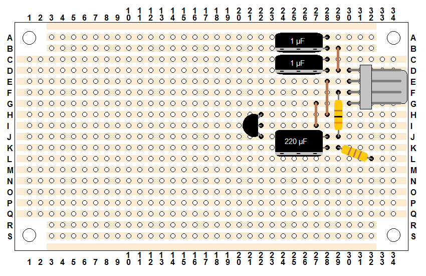
Step 11 – Output Ground
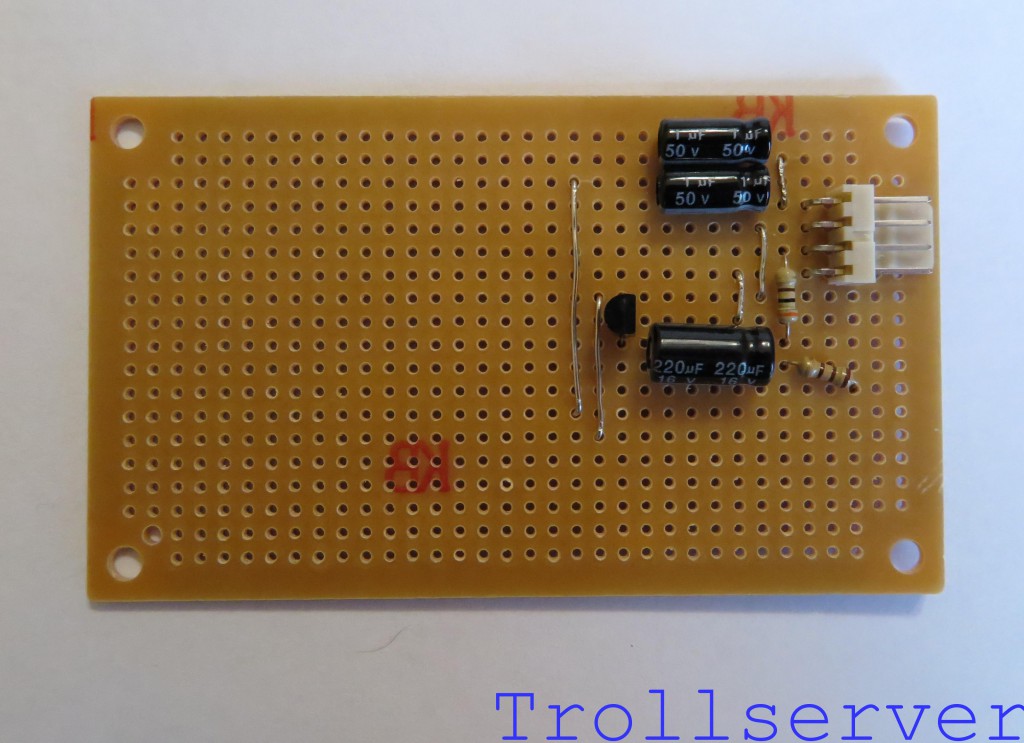
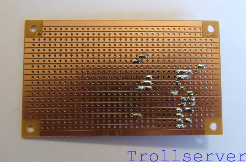
This is another piece of stripped wire. It is used to supply ground to the output connector. It goes through holes 21-H and 21-N. Don’t panic, it’s not actually as close to the transistor as shown here. I had to draw the transistor a little to one side so you could see which holes it goes through.
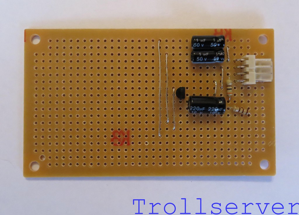
Just like the uninsulated wires used on the input side of the circuit, the next couple of steps all involve stripped wire on the front of the circuit board. The main difference is that these are significantly longer pieces of wire. Be sure you make the wire tight, flush to the circuit board, as close to a straight line as possible, and that none of the wires touch each other. Since they aren’t insulated, that would obviously cause problems.
Step 12 – Output Audio Channel 1
This is another piece of stripped wire. It is used to get the first channel of filtered audio to the output connector. It goes through holes 20-C and 20-M. Try to line the wires up with the holes on the board to assist you in keeping the wires nice and straight.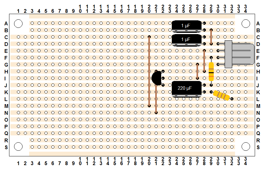
Step 13 – Output Audio Channel 2
This is another piece of stripped wire. It is used to get the second channel of filtered audio to the output connector. It goes through holes 19-A and 19-O.
Head over to Part 3 for the exciting conclusion of the circuit construction.
To jump between posts in this series, please visit the NES Mod Index.
