NES Toploader AV Mod – Circuit Construction – Part 3
To jump between posts in this series, please visit the NES Mod Index.
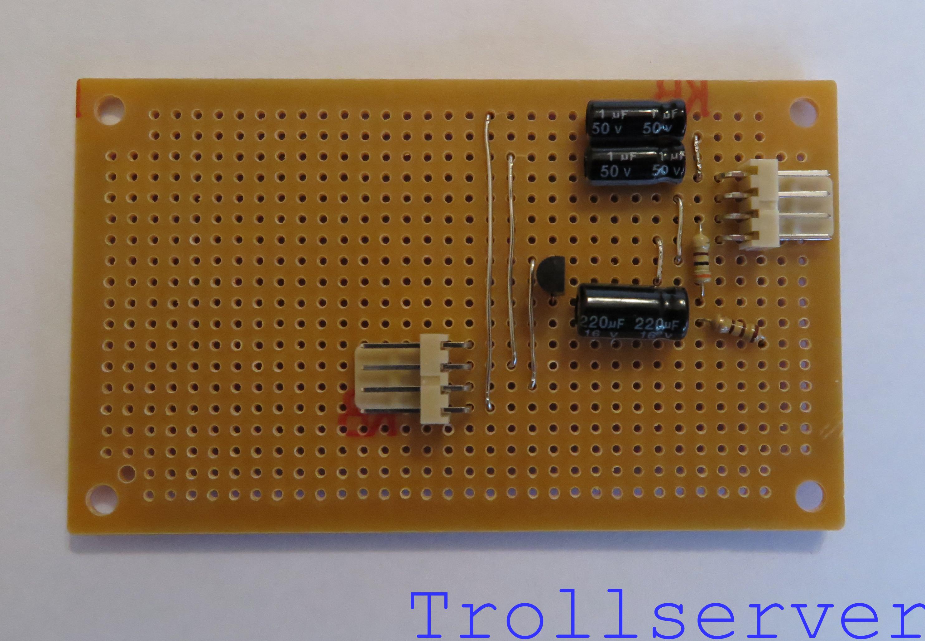
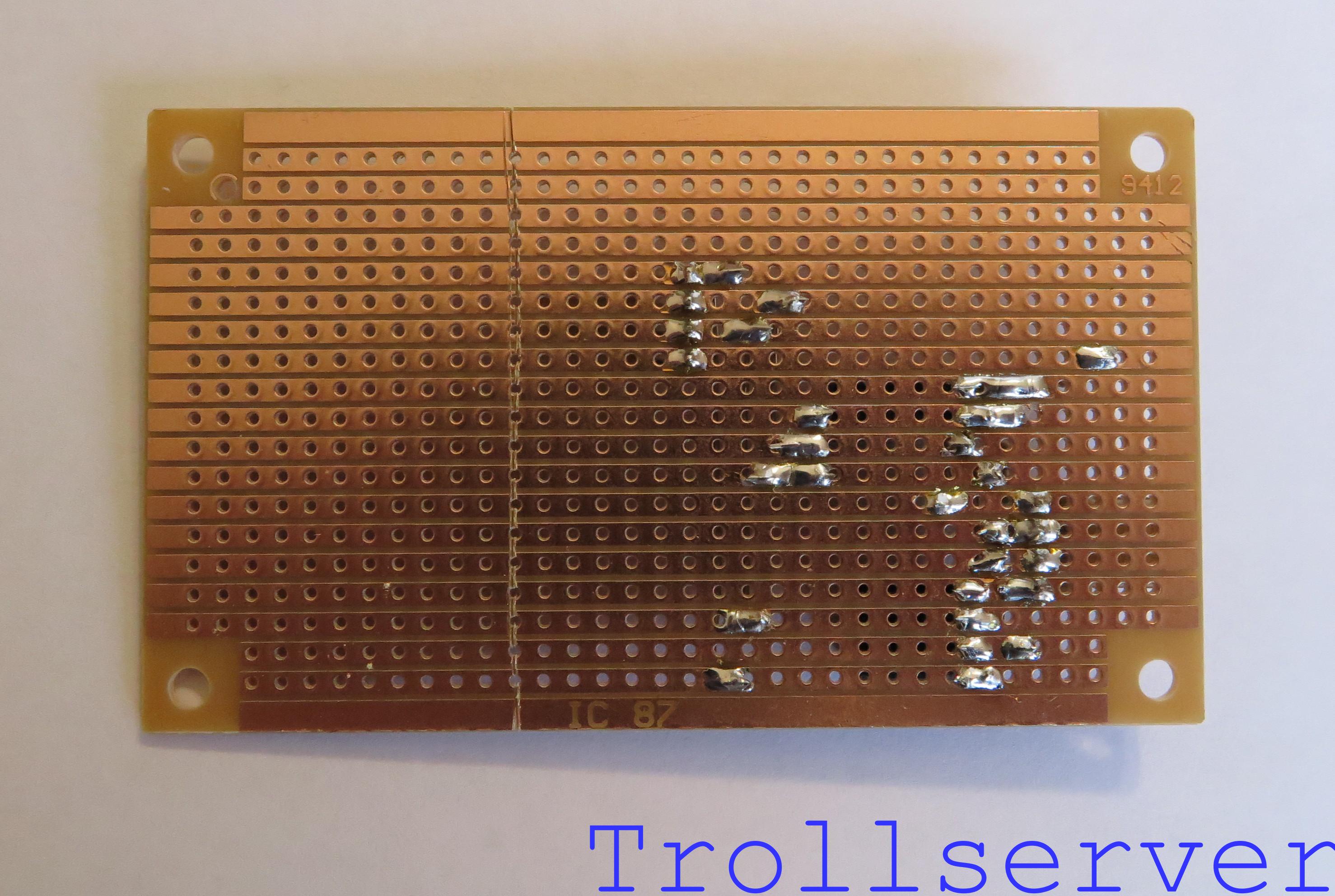
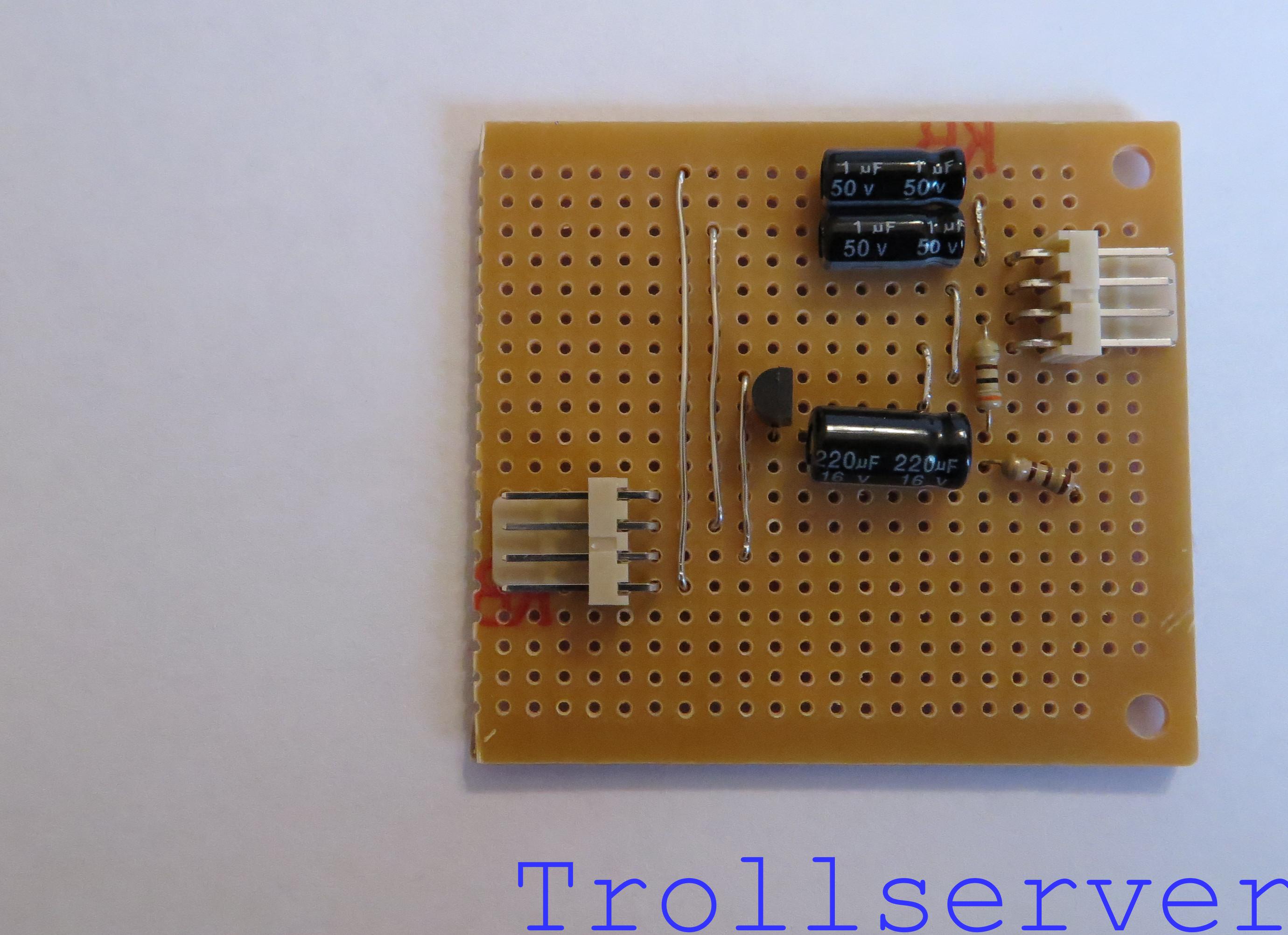
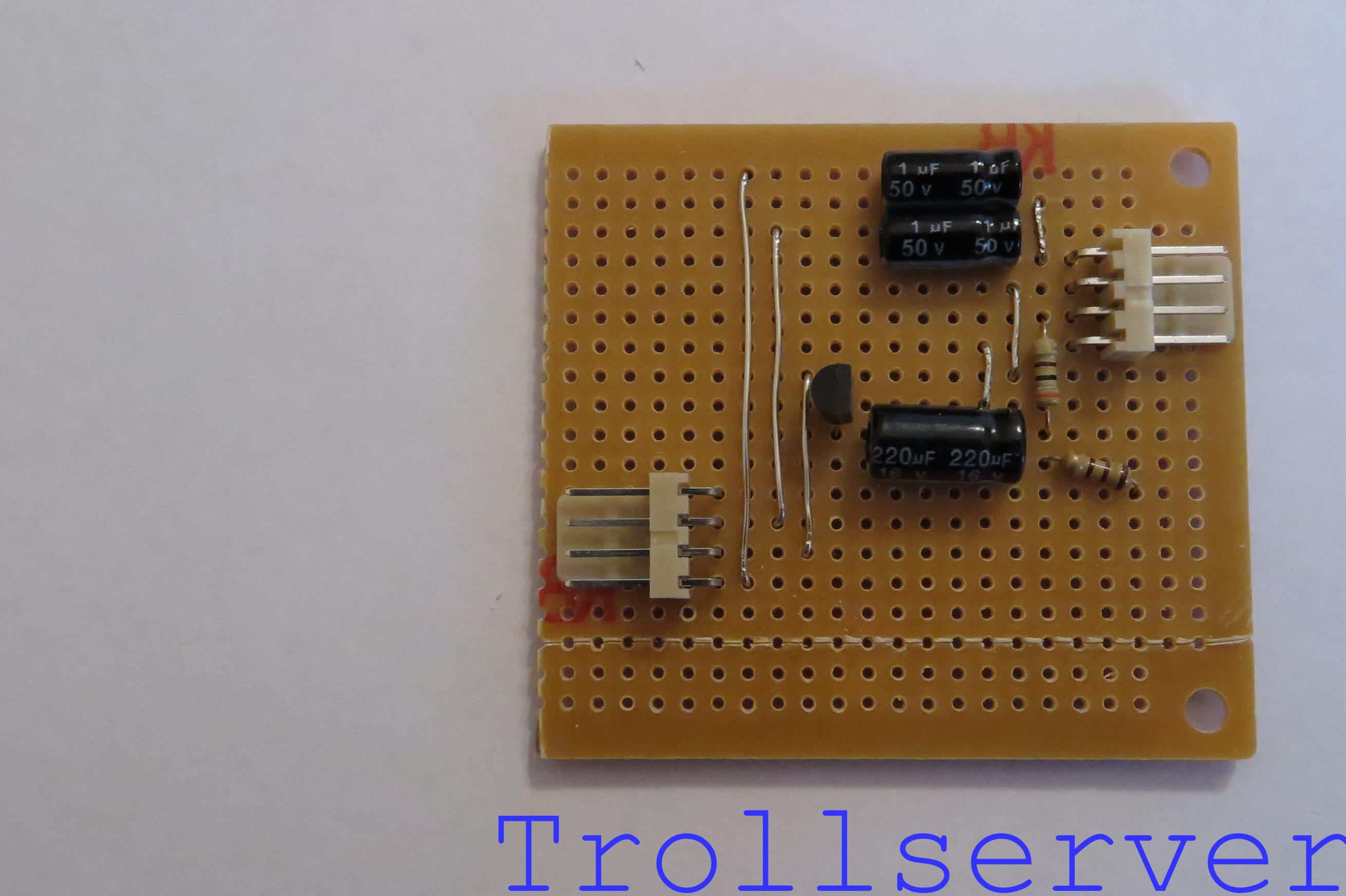
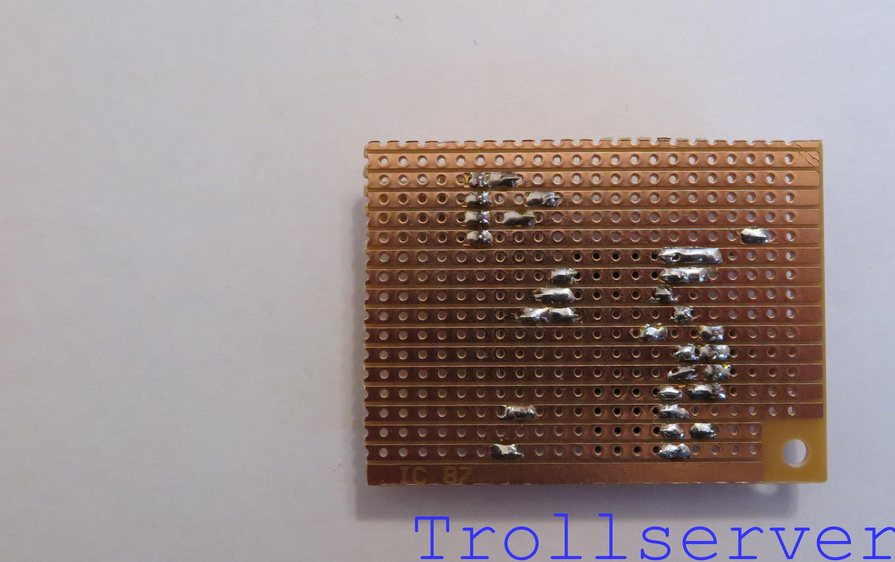
This is the third part of the instructions for building the circuit. If your board doesn’t look pretty close to the first picture on this post, you may need to go back to Part 1 or Part 2 to catch up.
Step 14 – Output Connector
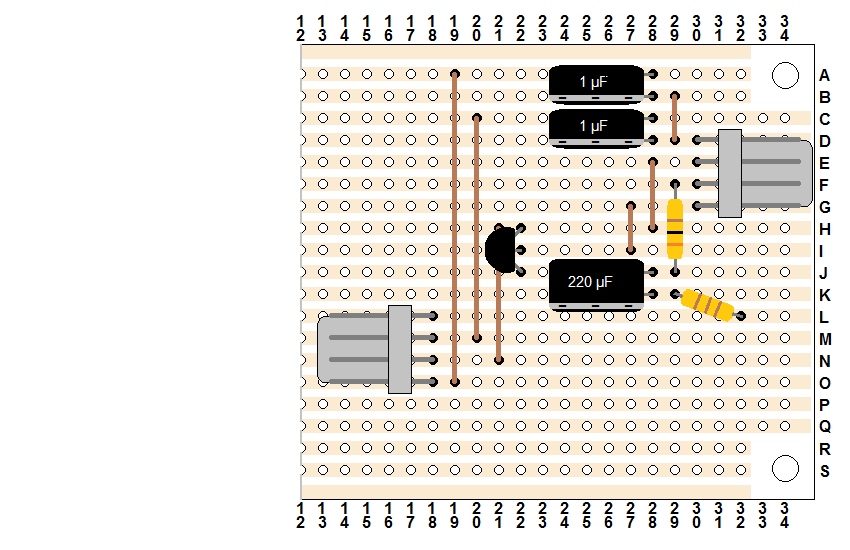
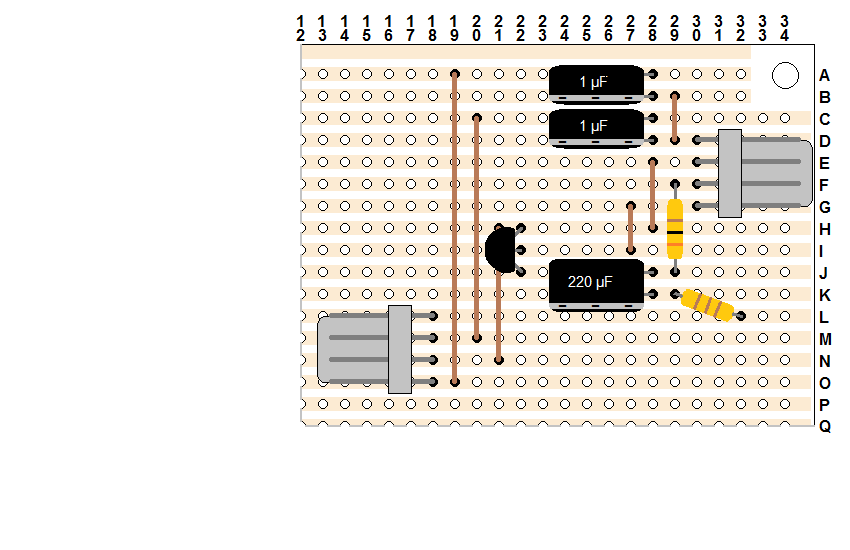
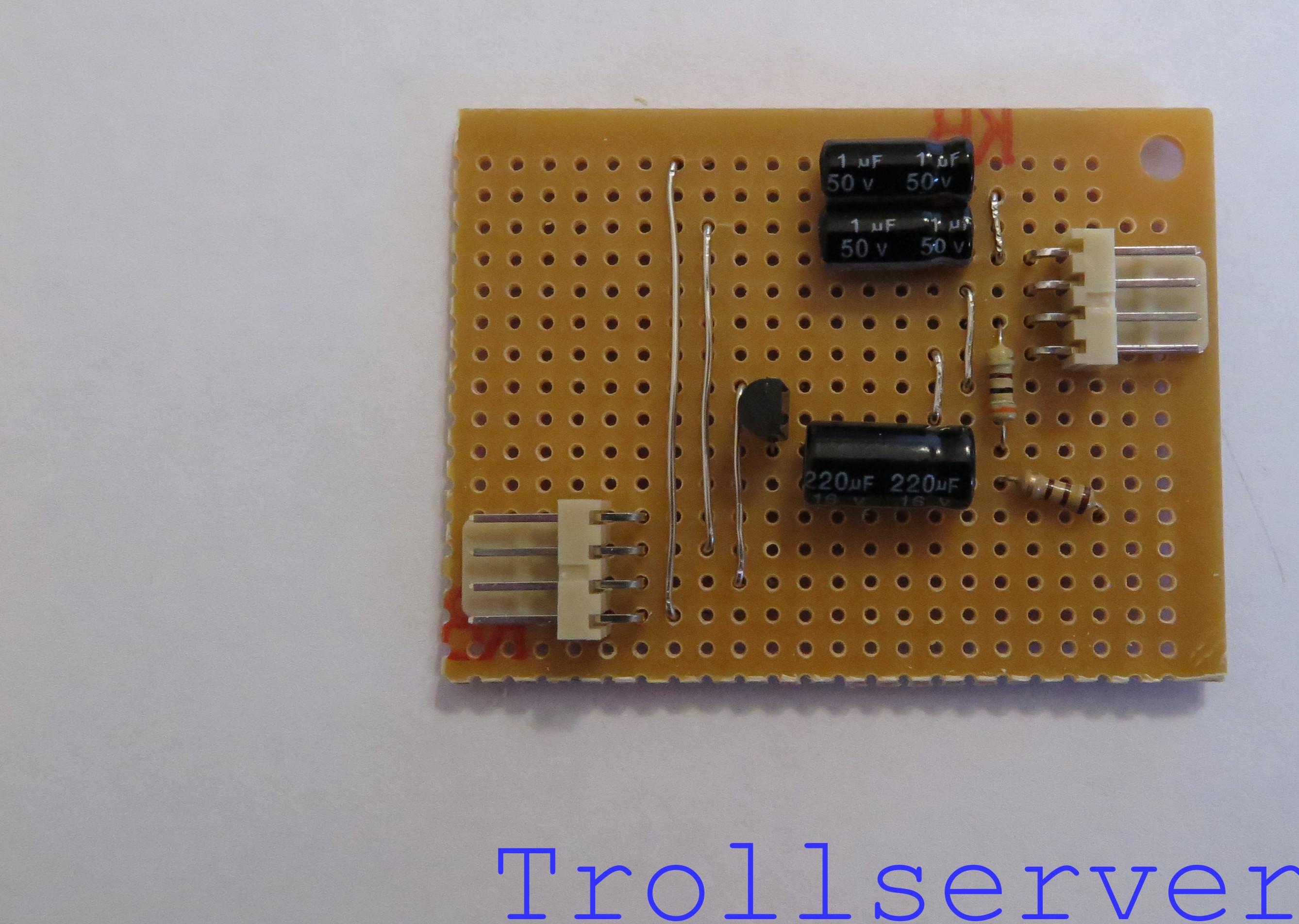
This is the output connector that will take all of the fancy signals we just made (and ground) and provide them to the RCA jacks that will be on the back of the NES when we are done. It faces the opposite direction of the input connector and goes through holes 18-L, 18-M, 18-N, and 18-O. This completes the actual circuit construction, but I recommend you continue on to the remaining steps for trimming and protecting the circuit board.

Step 15 – Score the Side of the Board
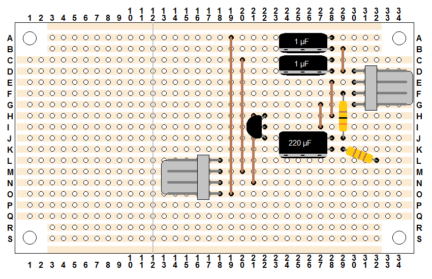
Using a razor blade or X-Acto knife carefully score the board through column 12 (the gray vertical line in the diagram below). Do this several times to make a good and deep series of scores. If you want you can also score the back of the board too, but make sure you line up where you are making the score marks carefully. I prefer to score both sides since I think it tends to result in a cleaner break.
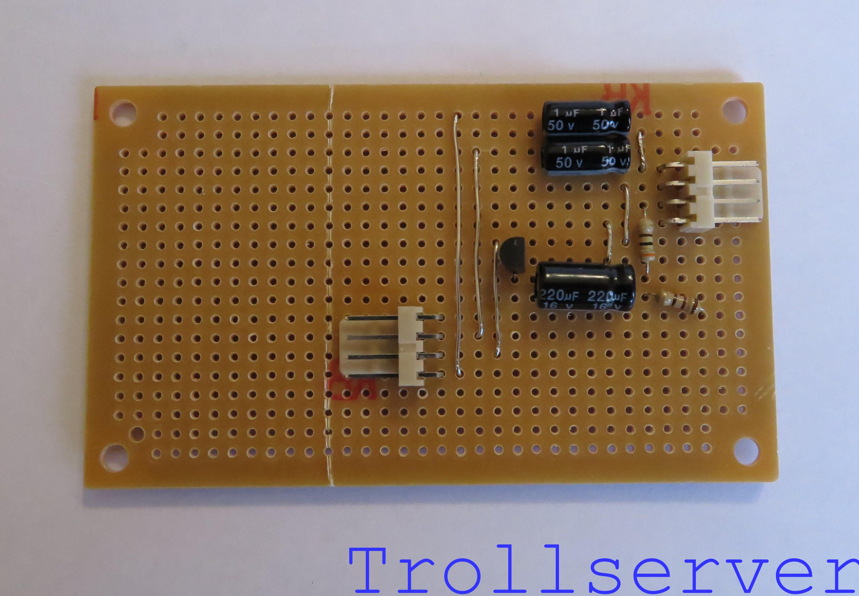
Step 16 – Trim the Side of the Board
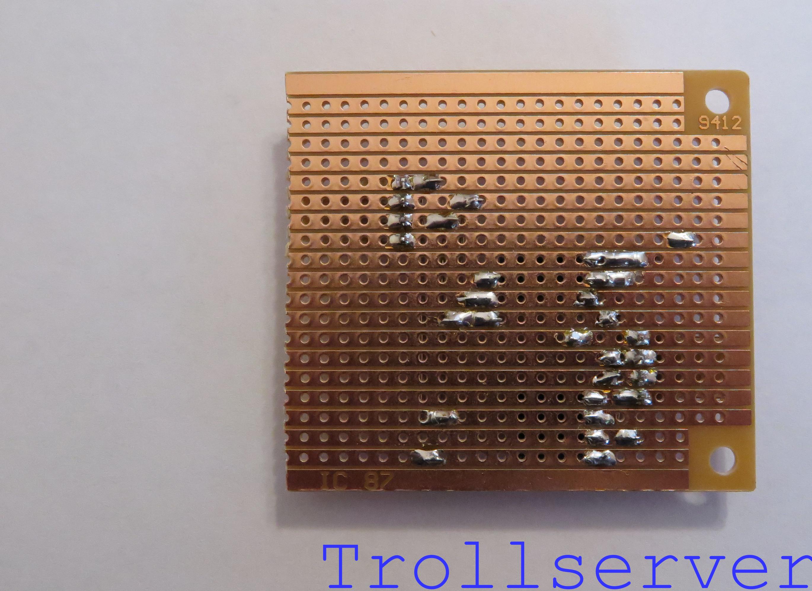
Gently bend the board so you are pushing forward from the back of the board behind your score marks and pushing the outer edges back. If you have scored it well enough the board should neatly snap where it was scored.
Step 17 – Score the Bottom of the Board
Using a razor blade or X-Acto knife carefully score the board through row Q (the gray horizontal line in the diagram below). Do this several times to make a good and deep series of scores.

Step 18 – Trim the Bottom of the Board
Gently bend the board so you are pushing forward from the back of the board behind your score marks and pushing the outer edges back. If you have scored it well enough the board should neatly snap where it was scored.
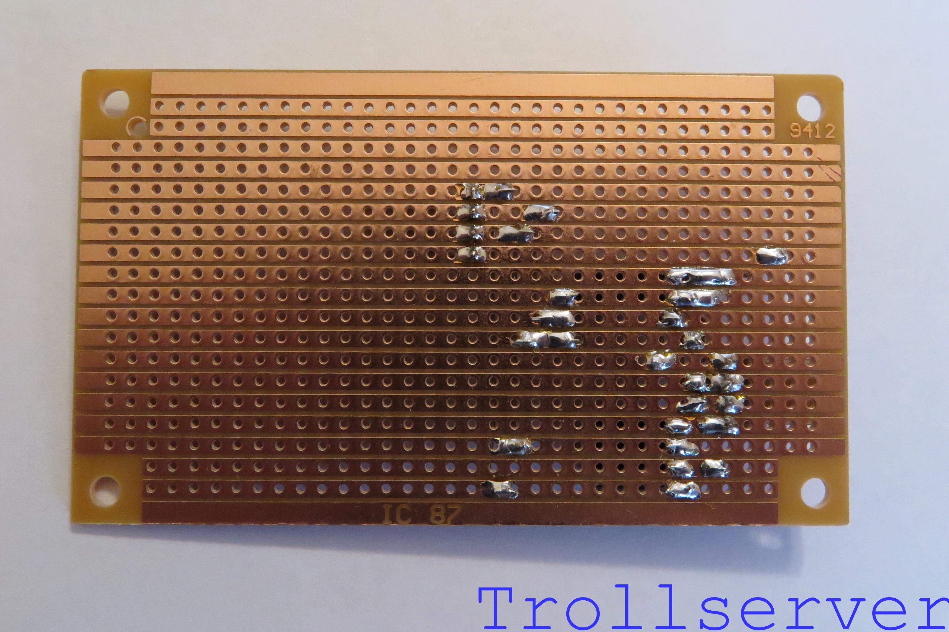
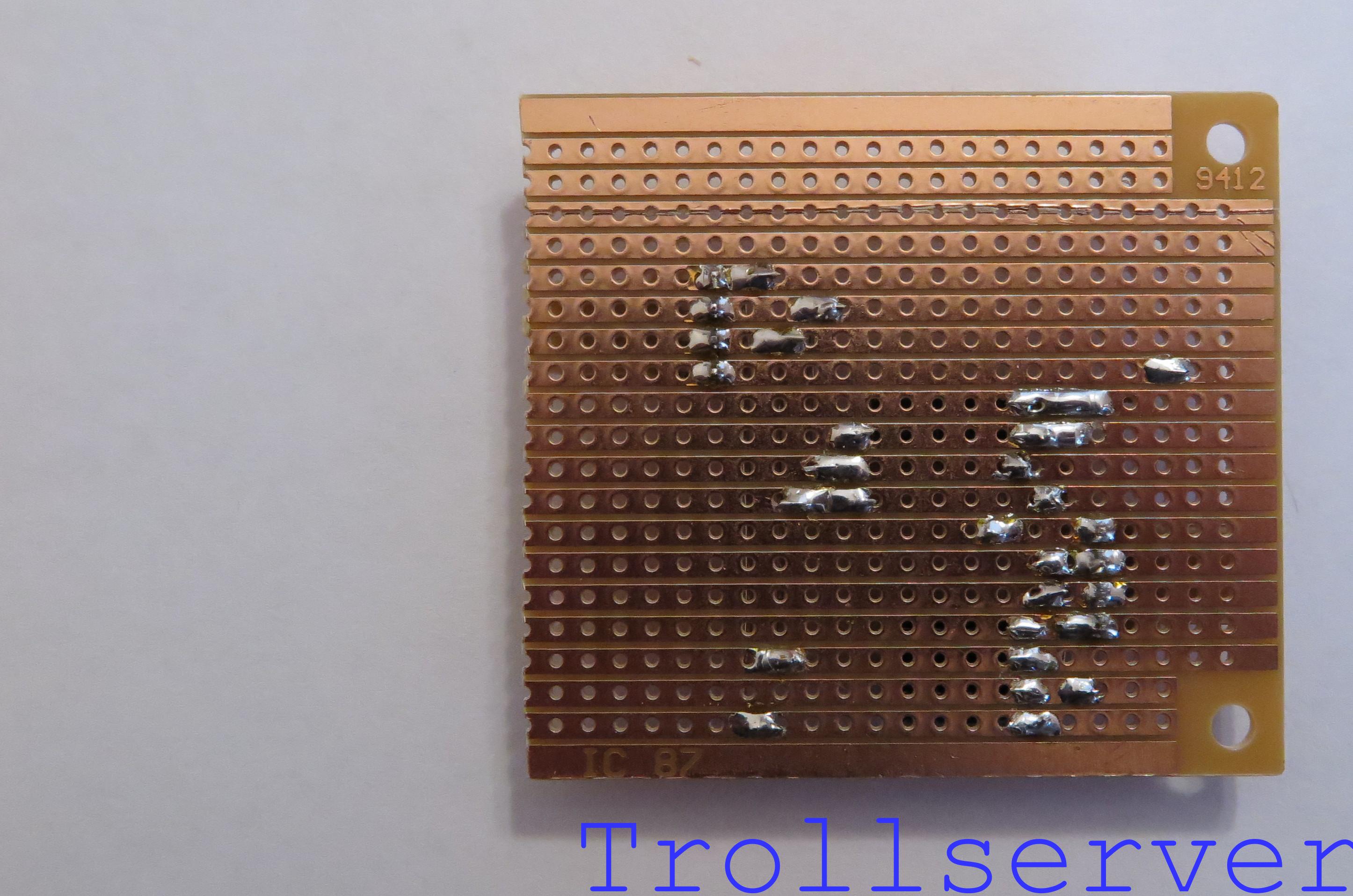
Step 19 – Protect the Back of the Circuit
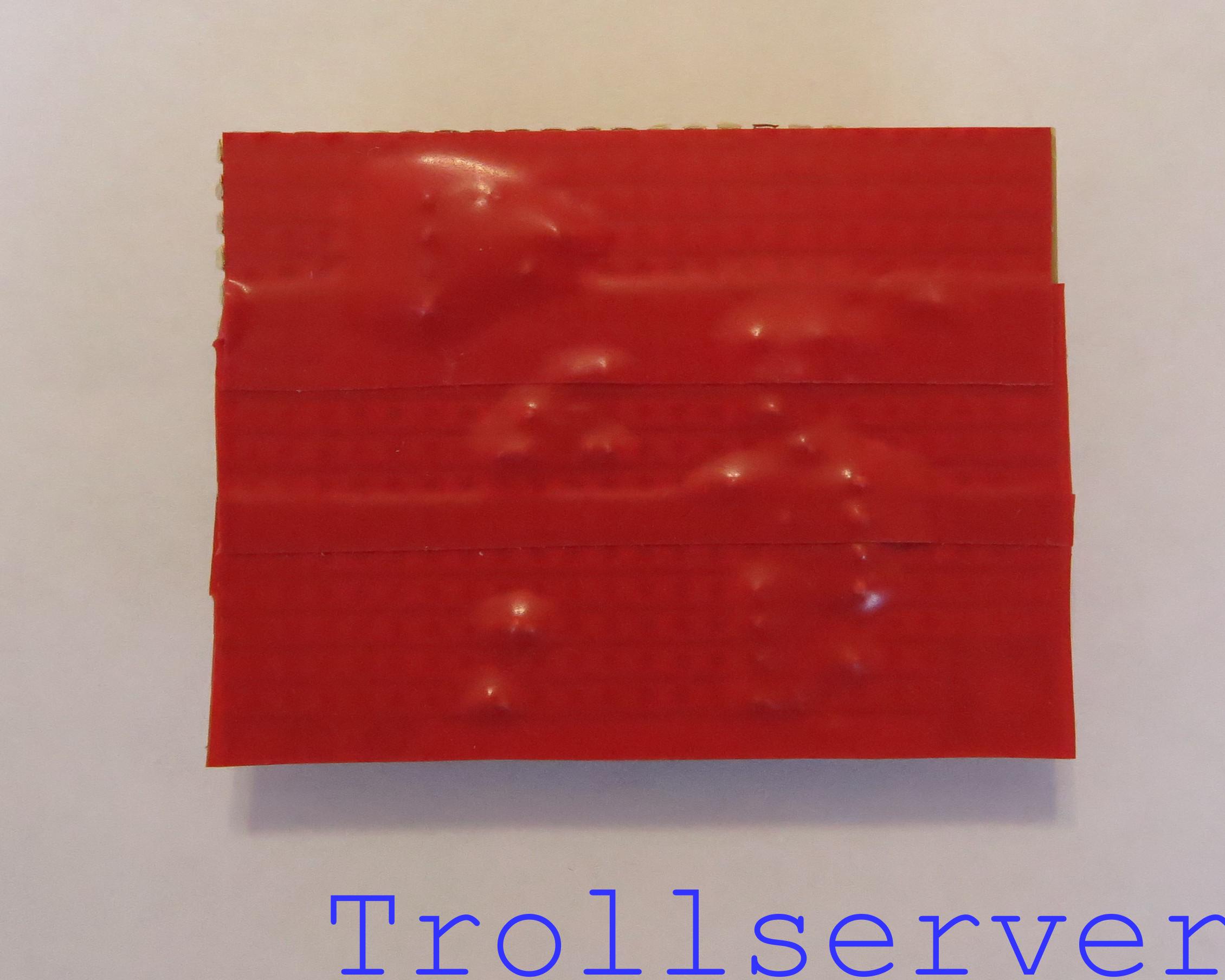
Now you just need to make sure the circuit doesn’t short out by touching something it shouldn’t once it’s installed in the NES. To do this, simply apply several overlapping strips of electrical tape on the side of the board where you did all your soldering.
Congratulations! If you’ve made it this far and haven’t burned your fingers or put any parts in the wrong position or direction, you should now have completed one of the hardest parts of doing the NES AV Mod and you haven’t even needed to touch your NES yet so it’s nice and safe still. (For now. 😉 )
To jump between posts in this series, please visit the NES Mod Index.