Category Archives: Electronics

NES Toploader AV Mod – Output Comparison

To jump between posts in this series, please visit the NES Mod Index.

This post documents my efforts to capture before and after videos of the NES AV mod.  It represents literally weeks of attempting to get a good recording of a few games both before and after the mod.  This was further complicated by the fact that once a NES is modified to have an AV mod the way I describe it in these articles, there is no going back.  Thus I actually bought a second NES Toploader for the before videos and used one I’d previously modified for the after.  It’s a little backwards I guess, but I promise the NES Toploader that I modified through this series of posts works perfectly, so it’s not really cheating.

These videos are all of the demos from the games so they are essentially identical before and after.  I did this to keep my less than awesome playing skills from making the videos different.  For each pair of videos I’ll try to point out some of the more hideous problems in the before video and when you watch the after video you can simply note how much improved they are.

First, I compared the game that almost everyone has multiple copies of.  Good old Super Mario Bros.  The changes on this one are mostly visible in the blue sky and the general blurriness.

Super Mario Bros – Before

Super Mario Bros – After

Now with that behind us, I figured it was time to get into other games that really show just how bad it is.  After all, it’s my opinion that all NES Toploaders should be modified with the AV mod.  Next in the line up is a comparison of Contra before and after the mod.  Note the blue of the water in the first part of the demo and the gray color of the walls in the second part.

Contra – Before

Contra – After

Finally I’d like to show you RC Pro-AM and I apologize in advance that the title screen plays music and does nothing else interesting for almost 30 seconds before going to the demo.  (Skip to around 25 seconds if you’d like to shorten it.)  For this game, note the cars in the title screen for visual artifacts and once the demo starts the green grass is especially bad but the road isn’t great either.

RC Pro-AM – Before

RC Pro-AM – After


Thanks for following along through this series.  Hopefully it’s been educational, informative, and useful.  If you’ve modified your NES Toploader, I hope you were successful.  If you were considering modifying a NES Toploader and haven’t purchased one yet because you wanted to make sure it was worth it, I hope I’ve convinced you.


To jump between posts in this series, please visit the NES Mod Index.
NES Toploader AV Mod – Reassembly

To jump between posts in this series, please visit the NES Mod Index.
 

Now it’s time to put it all back together.  This process is a lot like taking it apart, only backwards.


Step 1 – Carefully Flatten The Input Wires

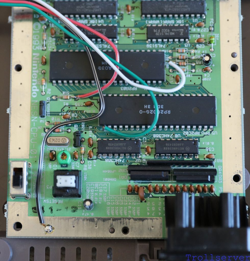
If you are like me, you’ve soldered your wires to the NES Motherboard and did no further messing with them before you tried it out.  That probably means your wires have no hope of fitting under the motherboard shield without a bit of work.  Gently flatten the wires so they are closer to the NES Motherboard and sort of go between components.  It doesn’t have to be perfect because the motherboard shield has quite a bit of clearance.  It should look a bit like this when you are done.

reassembly01


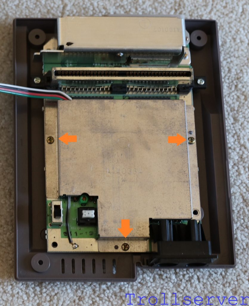
Step 2 – Put the Motherboard Shield Back On

Once your input wires are sufficiently flattened, you need to put the motherboard shield back on.  It uses the 3 Phillips head screws.  You may not have noticed when you removed the shield that there were actually 4 holes even though there were only 3 screws.  I’ve labeled the holes that need the screws in them with orange arrows to remind you where they go.

reassembly02


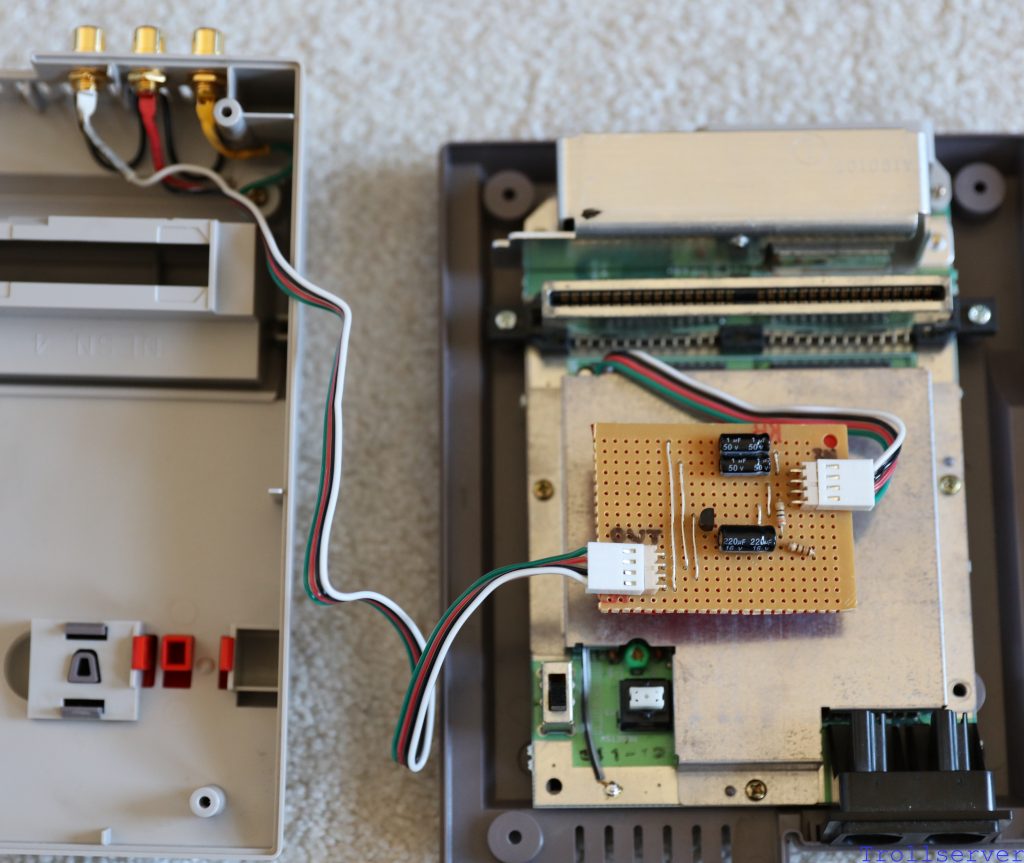
Step 3 – Connect and Position the Circuit Board

This step may already be partially complete if you did the Smoke Test as described in the previous post, but I will describe it anyway.

  1. Connect the wire that’s coming out from under the motherboard shield to the Input side of the circuit board.
  2. Connect the wire that goes over to your RCA jacks to the Output side of the circuit board.
  3. Carefully bend and twist the wires until they have the circuit board sitting comfortably near the middle of the motherboard shield.
  4. Double check that the spot where the input wires come around the shield is not pressed up against the cartridge slot.  It will make both closing the NES and inserting cartridges difficult if it’s left that way.

reassembly03


Step 4 – Close the NES

Now with things mostly in the right places, it’s really time to close it all up again.  This process can take a little time and be a bit of a pain because there is obviously more stuff in the NES than it left the factory with.  Be particularly careful getting the Heat Shield around the backs of your RCA jacks.  Just keep working it closer together and poking things back into place through the gap until everything is in there, nothing is blocked, and you can hold it closed without a lot of pressure.

Once you have everything lined up, flip the whole thing over and put the 4 case screws back in to hold it closed.  These are the screws that are the funny security style.  I haven’t provided a picture for where they go because there are 4 screws and 4 holes and by this point of the process I’m pretty sure you’ve got this one on your own.  🙂

This is what it should look like all closed up again from the front and the back.  Please note that your RCA jacks may have ended up in a different order, and that’s just fine.  I mostly just like to make sure the two audio ones are next to each other instead of having the video in between them.

reassembly04

And from the back.

reassembly05


Congratulations!  If you’ve gotten this far, you’ve completed the journey to a NES with improved graphics.  Now go play that bad boy and enjoy it.  The last post in this series is an output comparison.  A bit of before and after because it seemed like the right thing to do.


To jump between posts in this series, please visit the NES Mod Index.
NES Toploader AV Mod – Smoke Test

To jump between posts in this series, please visit the NES Mod Index.
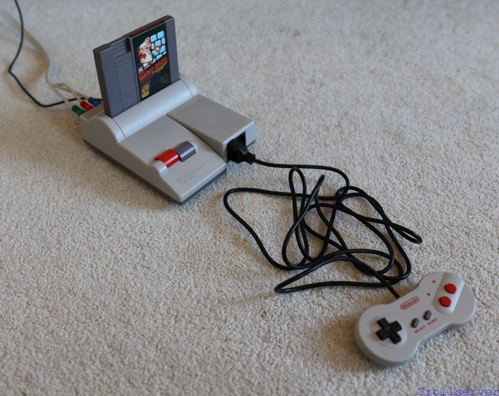
 

Now you’re essentially done with your NES Toploader AV Mod, and it’s almost time to squash everything back together into the NES and close it up.  Before you do, it’s probably a good idea to make sure everything works.  It would not be any fun to get it back together and realize you need to take it apart again to figure out what went wrong.  This is referred to as a “smoke test”.  I guess the original idea behind the name is to try something out and make sure nothing is making smoke or fire as a result.

Regardless of what you call this test, I highly recommend it.  You are up against Murphy and his law and it seems like every time I’ve ever done a smoke test, everything has been ok and when I haven’t, I’ve had to open it all up again to diagnose a problem.  Skip this step at your own peril, but don’t complain to me if Murphy comes to get you.


Step 1 – Gather Up Your NES

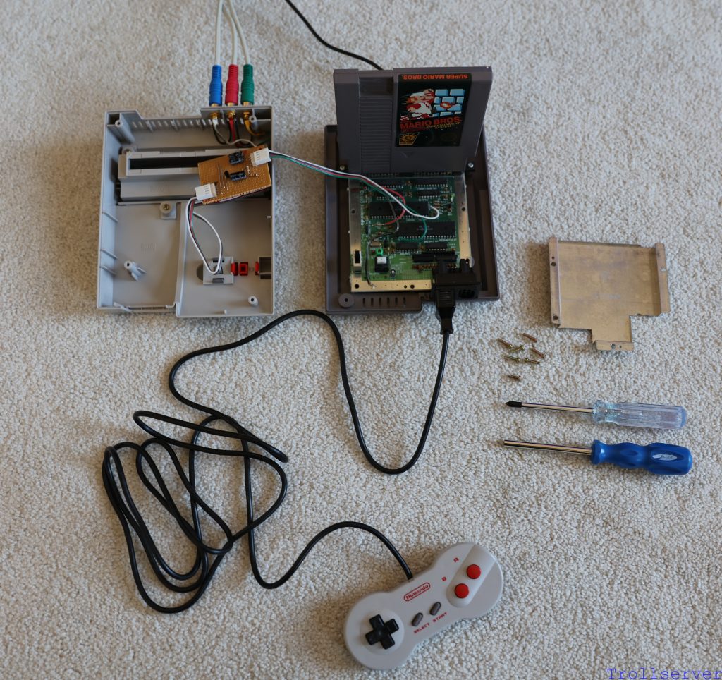
You need the following parts with you when you get to a TV:

  • The NES Top Shell (with its fancy new RCA Jacks waiting to talk to the TV)
  • The NES Bottom Shell (with the motherboard and a wire waiting to give your circuit signals)
  • The Circuit Board you built (waiting to do its job)
  • The NES power supply (wouldn’t be much good if you can’t turn it on)
  • A set of composite wires (so you can hook it to the TV)
  • A NES Game (any game will do as long as you know it works)
  • A NES Joystick (playing is the best way to make sure things work)
  • A comfy seat (you may end up playing for longer than you expected because it’s fun)


Step 2 – Hook Everything Together

  1. Place the NES Bottom Shell on whatever surface you have available for this setup.  Mine always seems to be the floor.  Plenty of room and no worries about things falling off of anything.
  2. Place the NES Top Shell next to the NES Bottom Shell.  I usually place the top part to the left side of the bottom because that’s which way I have the circuit board set up.  Meaning specifically that the output is to the left.
  3. Connect the NES Top Shell’s 4-pin connector to the output side of your circuit board.
  4. Connect the NES Bottom Shell’s 4-pin connector to the input side of your circuit board.
  5. Plug the power supply into the appropriate spot on the NES Bottom Shell.
  6. Plug the joystick into the player 1 port on the NES Bottom Shell.
  7. Gently put a game into the cartridge slot.  Be careful here as you don’t have all of the convenient plastic to help guide you into the cartridge slot smoothly.  All the plastic that helps to guide cartridges into the system are part of the NES Top Shell which is sitting somewhere off to the side instead of doing its job at the moment.
  8. Connect the composite wires to the RCA Jacks on the NES Top Shell and to your TV.
  9. Turn on your TV and select the appropriate input for a composite signal.
  10. Plug in the NES power supply.

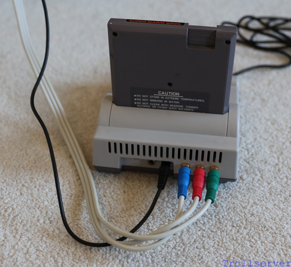
If you’ve got everything you need and it’s all hooked together properly it should look a bit like this.

smoke_test01


Step 3 – Make Sure It Works

  1. Locate the power switch on the NES Bottom Shell.  It’s the large switch in the bottom left corner of the motherboard.  Turn on the system by pushing the switch toward the cartridge slot.
  2. Play your game for a couple minutes.  (Or more, because it’s fun and you’ve lost track of time.)
  3. Marvel at the amazing graphics and your awesome electronics skills.


Troubleshooting

  • Nothing happened! – I know it’s silly, but make absolutely sure:
    • Your TV is on.
    • The correct input is selected on your TV.
    • Your NES power supply is plugged in to an outlet that is actually providing power.   (I’ve actually plugged it into an outlet that was on a switch once without knowing it.)
    • Your composite wires are connected on both ends.  (Specifically, both to the TV and to the NES.)
    • Any AV switches you have in your setup are in the correct setting to let a signal through.  (I have about 15 consoles connected to the same TV so I have to make sure multiple switches are in the right positions.)
    • You’ve got the power switch in the correct position.  (Power is on when the switch is toward the cartridge slot.)
    • You have the input and output sides of your circuit board connected to the correct 4-pin connectors.  Backwards is not good.  Label your board with a Sharpie if you have to, after all it’ll be neatly inside the NES when you are done so no one will see your notes.
  • Audio but No Video! – This one is a little trickier, but I’ve had it happen to me:
    • Are you sure you bought the correct transistor?  I had the correct type of transistor, but where the pins were not in the order I expected.  The result was that I was trying to amplify +5 volts with my video signal instead of the other way around.  That results in no video signal at all.
    • Did you put the video capacitor onto your circuit board in the wrong direction?  If you got the polarity backwards, the whole circuit won’t work properly.
  • Video but No Audio! – I’ve never actually had this one happen to me, but it’s possible.
    • Did you put either of the audio capacitors onto your circuit board in the wrong direction?  If you got the polarity backwards, the whole circuit won’t work properly.
  • Random Other Problem! – If something else doesn’t work correctly, you may have any one of a vast collection of actual issues:
    • Did you build the circuit board correctly?
      • All of the wires, connectors, components, etc., are soldered correctly and in the correct places?
      • Are your capacitors facing the correct direction so the polarity is correct?
      • Did you accidentally connect two rows of the stripboard when soldering things in place?
    • Did any wire soldered to your RCA Jacks or to the NES Motherboard come loose?
    • Did you accidentally break a capacitor on the NES Motherboard when working on PPU Pin 21?
    • Did your NES work correctly before you started this operation?
      • Does your power brick work?
      • Is the game clean, functional, and inserted correctly?
    • [Insert other theories here about what may have gone wrong and equally valid theories about how to fix those problems.]


If everything worked correctly it’s time to button everything up again and buckle in for some serious old school gaming.  The next post is all about how to put everything back together again.


To jump between posts in this series, please visit the NES Mod Index.
1 2 3 6