NES Toploader AV Mod – Circuit Construction – Part 1
To jump between posts in this series, please visit the NES Mod Index.
Now it’s time to build the circuit. This process is going to involve some careful placement of parts onto the stripboard and it’s super easy to “miss” when placing something. To help reduce the chances of this happening, I’ve built these instructions in a way that allows you to use other parts you’ve already placed on the board as reference points for parts you are about to place. The side effect of this approach is that I can’t break the circuit into logical areas like “the audio half” or “the video half” because I’ll be mixing and matching which part of the circuit is being worked on in any given step.
I have also created a series of diagrams, labeled them like an over-sized chess board, and tried to explain what I’m doing in each step in English as well as possible. My best advice is that you simply go slowly and quadruple check what you are doing before you solder something in place. Good luck and have fun! Let’s get started…
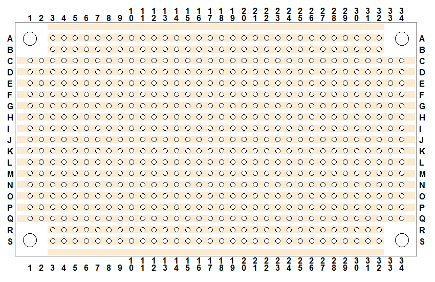
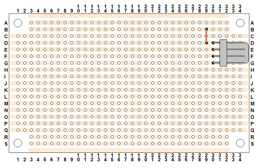
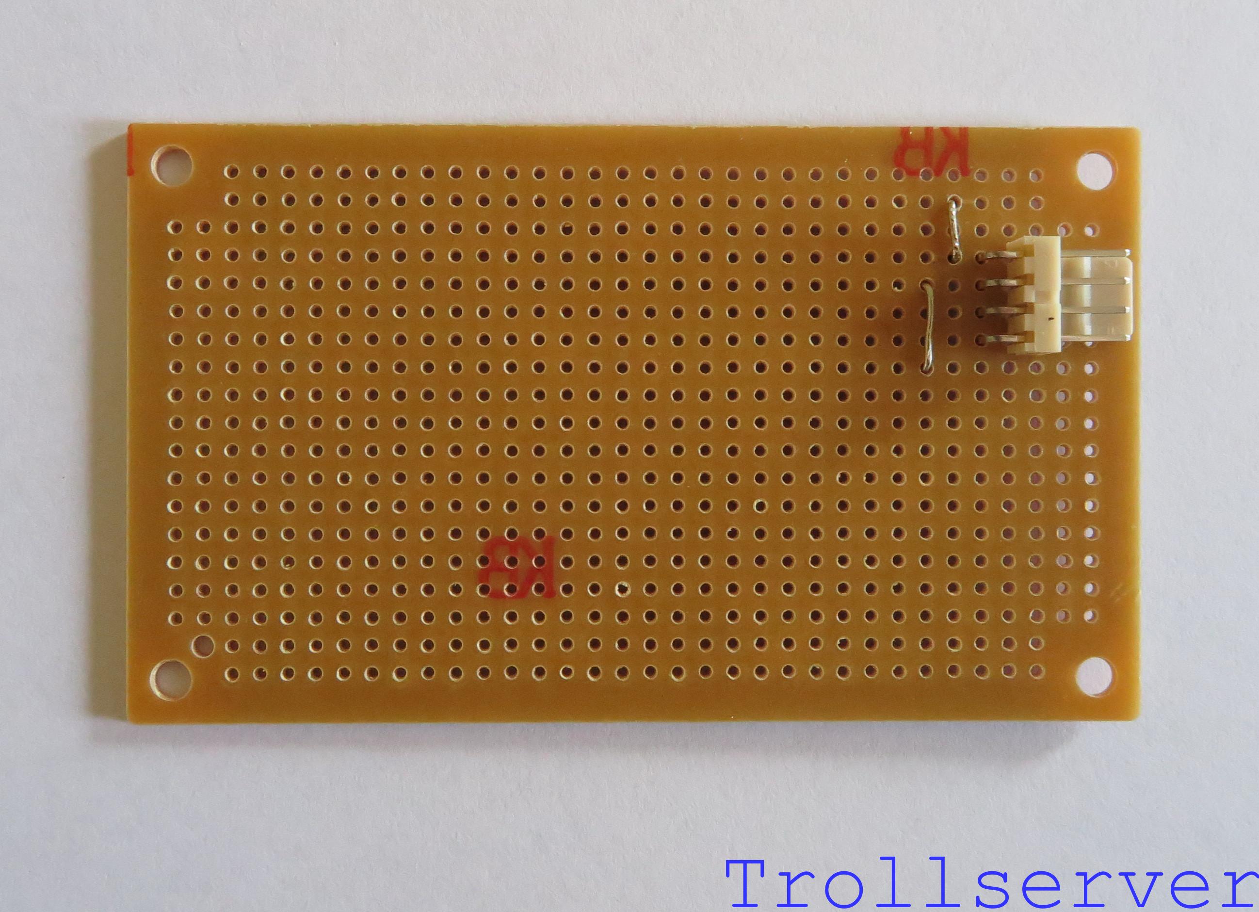
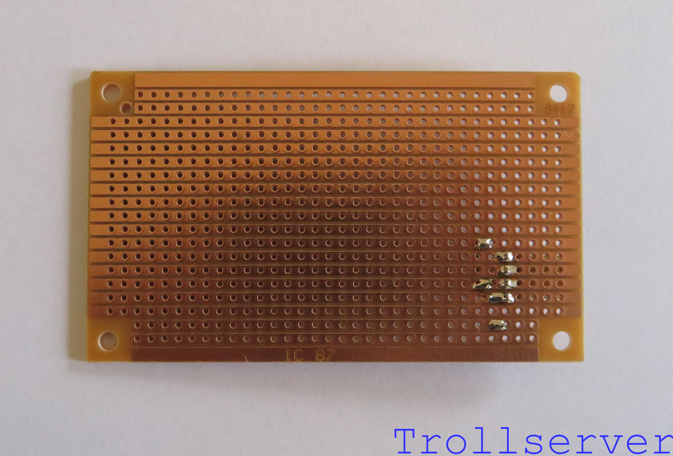
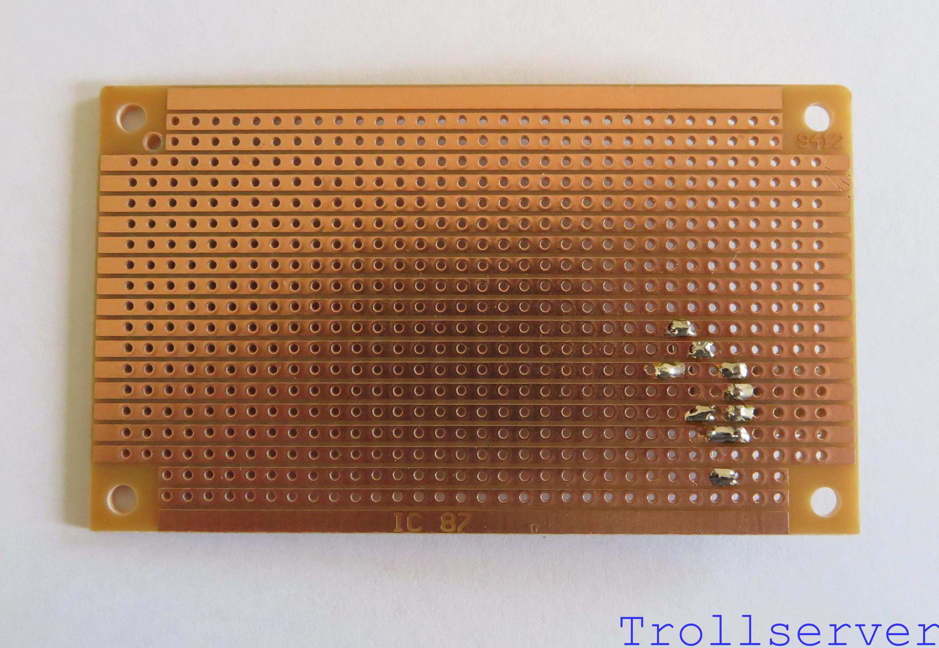
Step 0 – A blank Stripboard.
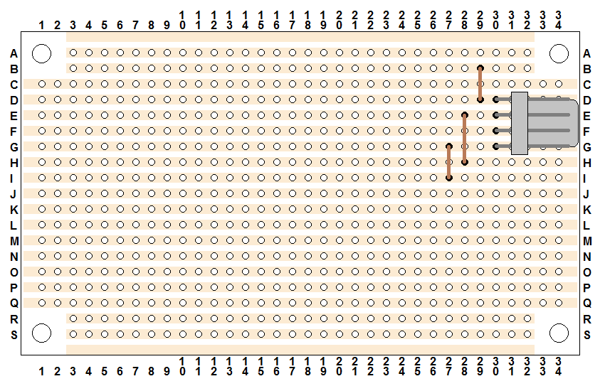
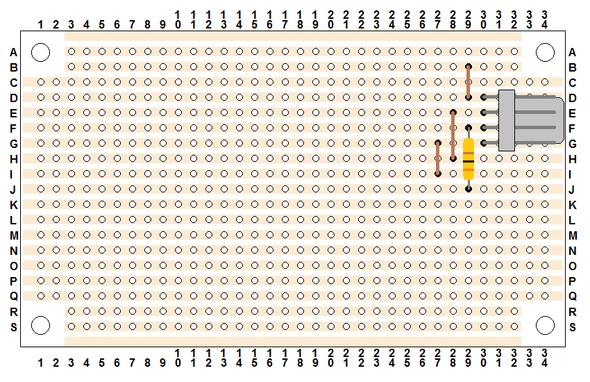
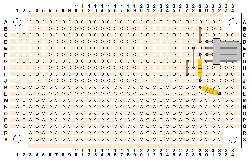
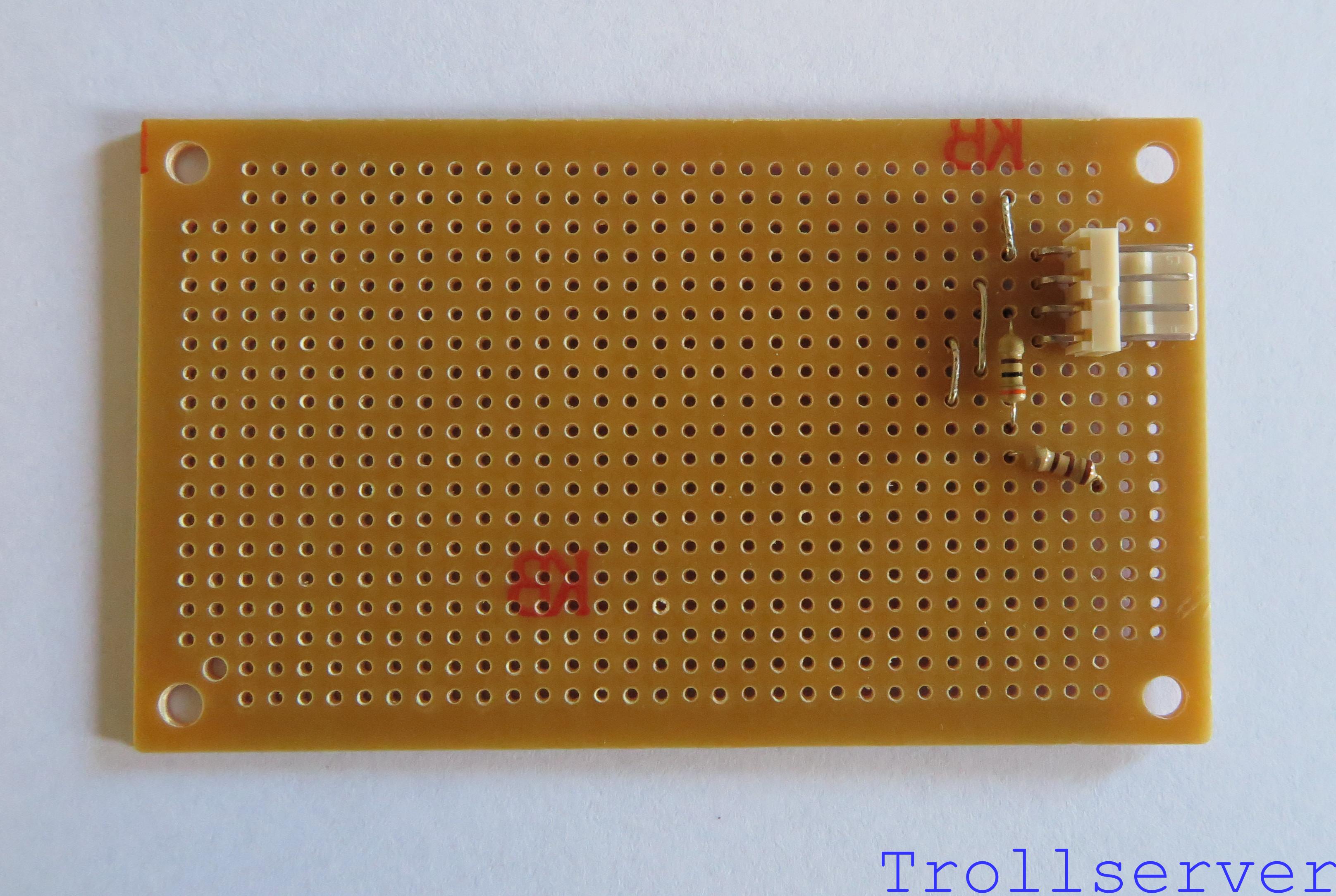
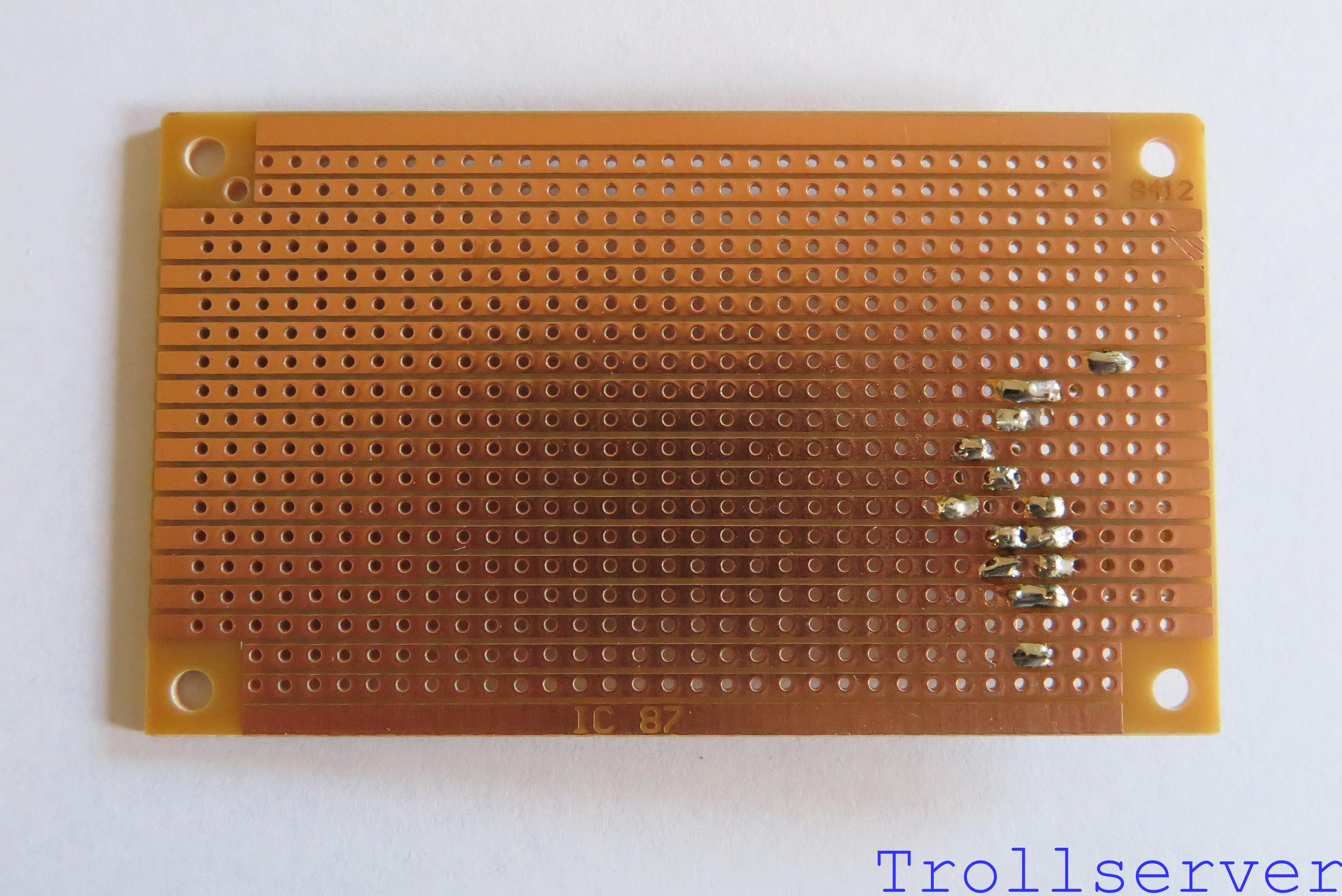
My diagram should very closely resemble the stripboard you have in front of you if you bought the one I recommended. I follow a couple of conventions through this process to try to make what is happening a little more obvious. For the sake of these instructions, I define the “front” of the stripboard as the side of the board that does NOT have the copper strips on it. The “back” is the side where you can see all the copper strips. Even though my hand drawn diagrams show the copper strips, they are provided only for electrical reference as my diagrams all show the stripboard from the front. You ALWAYS place parts on the front of the stripboard. When a hole in the stripboard has something in it, I fill it in black so it’s obvious which hole was used to go through the stripboard.
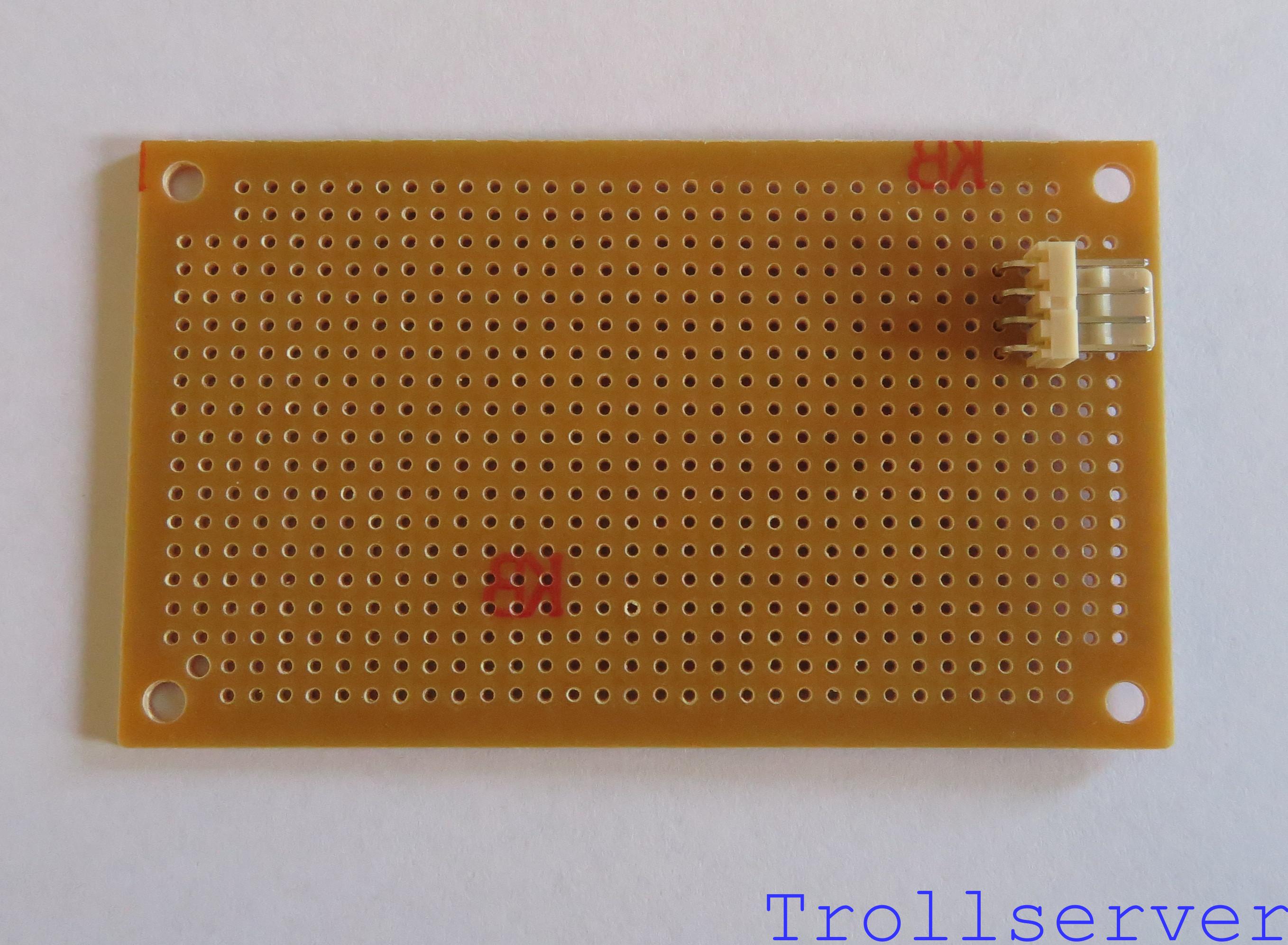
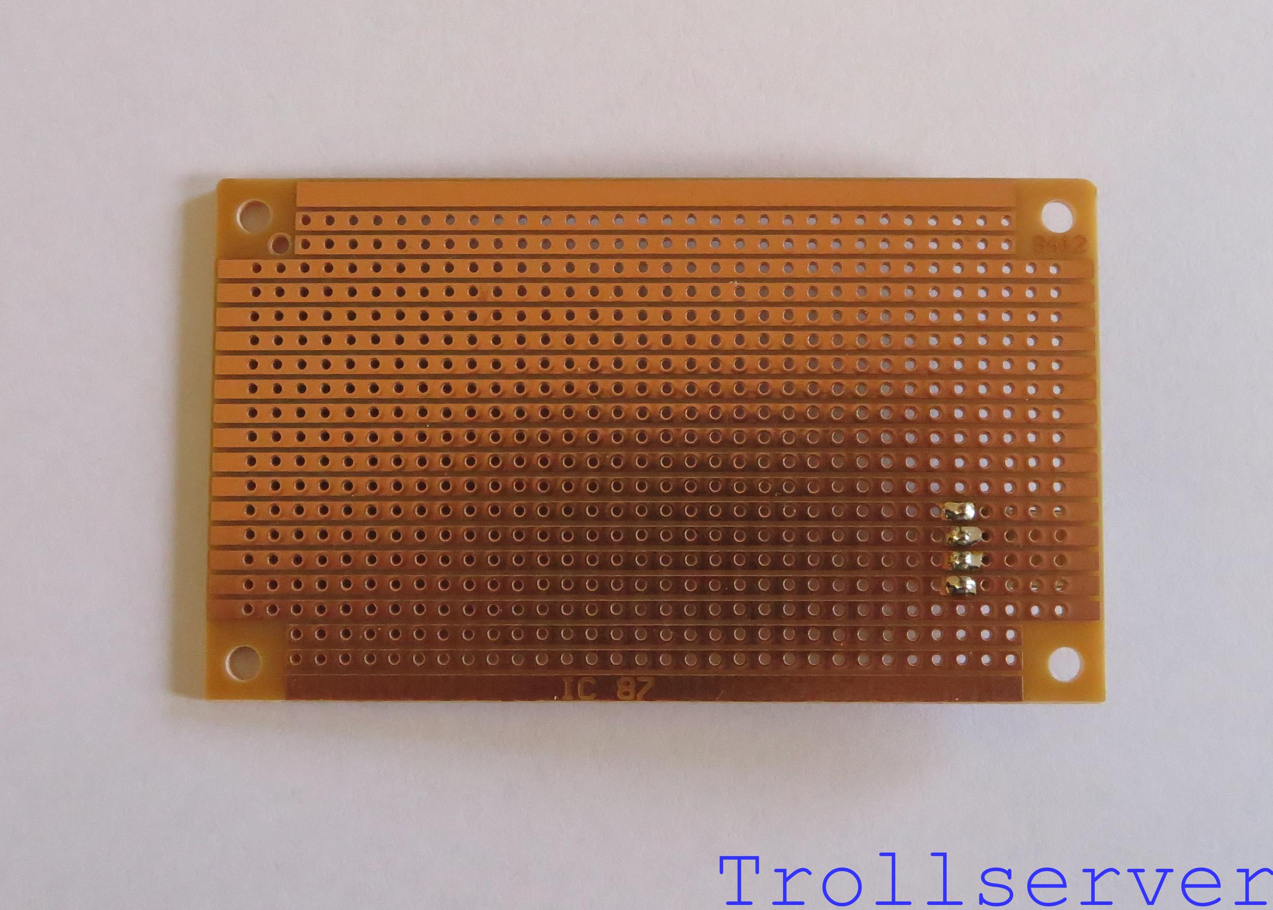
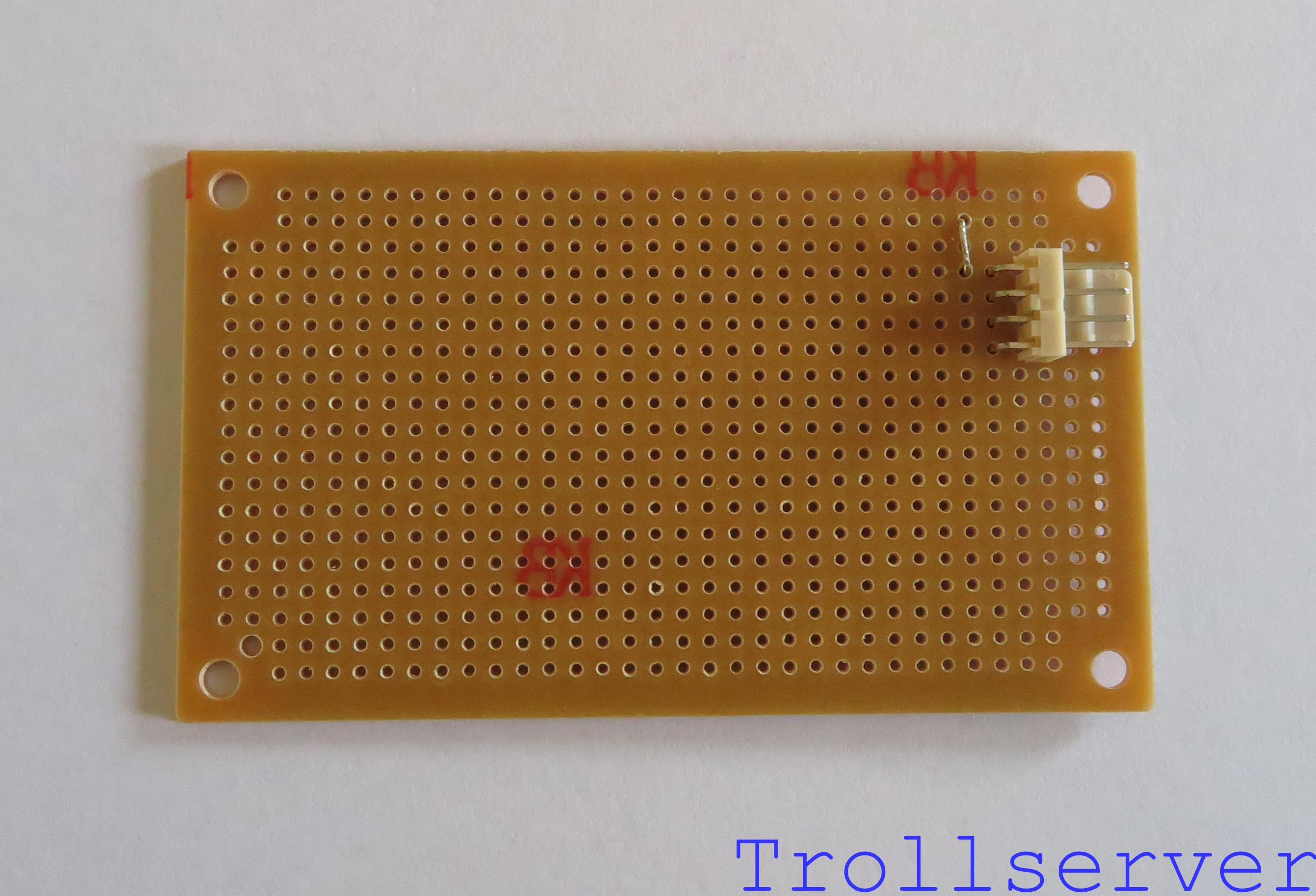
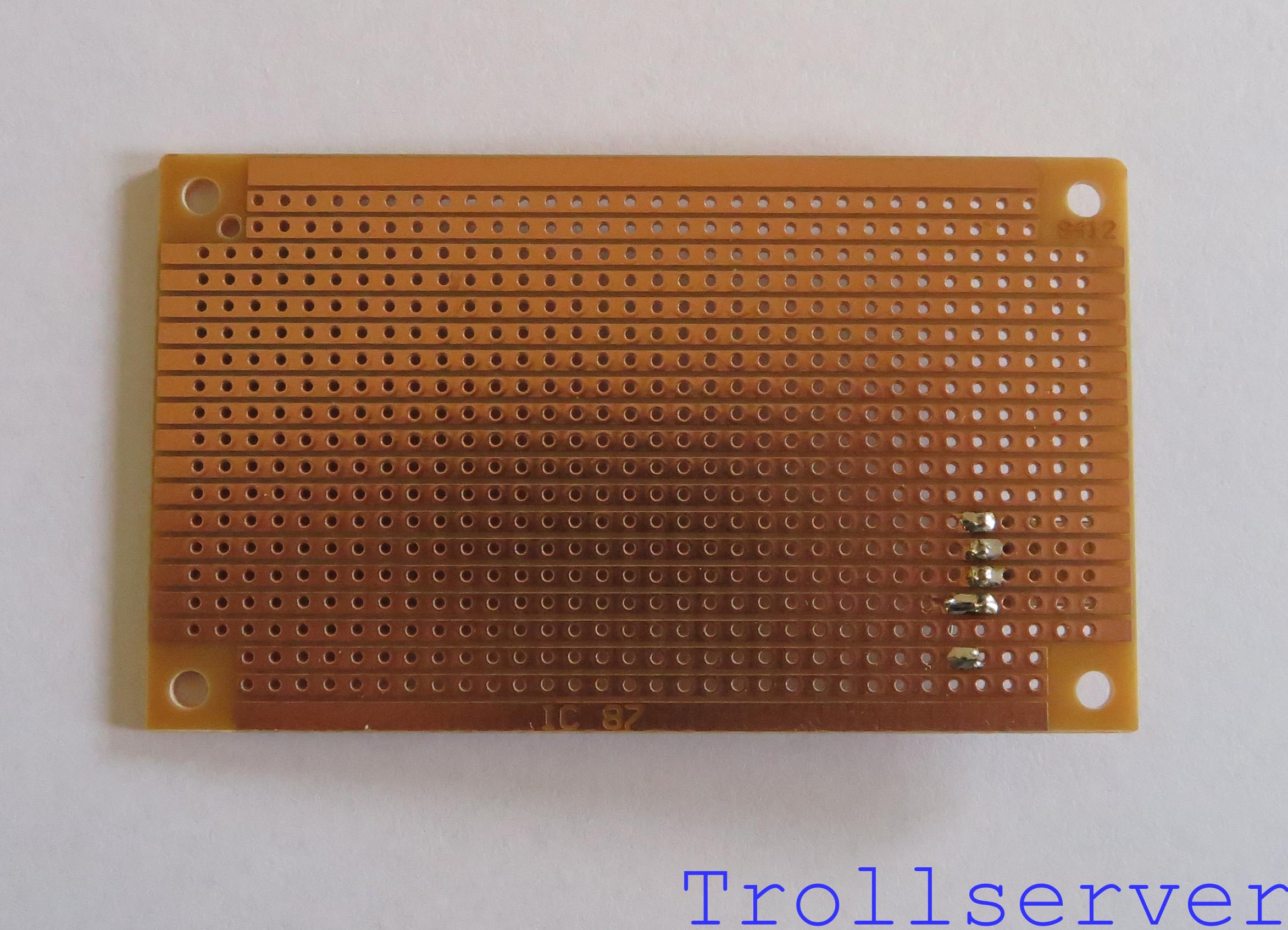
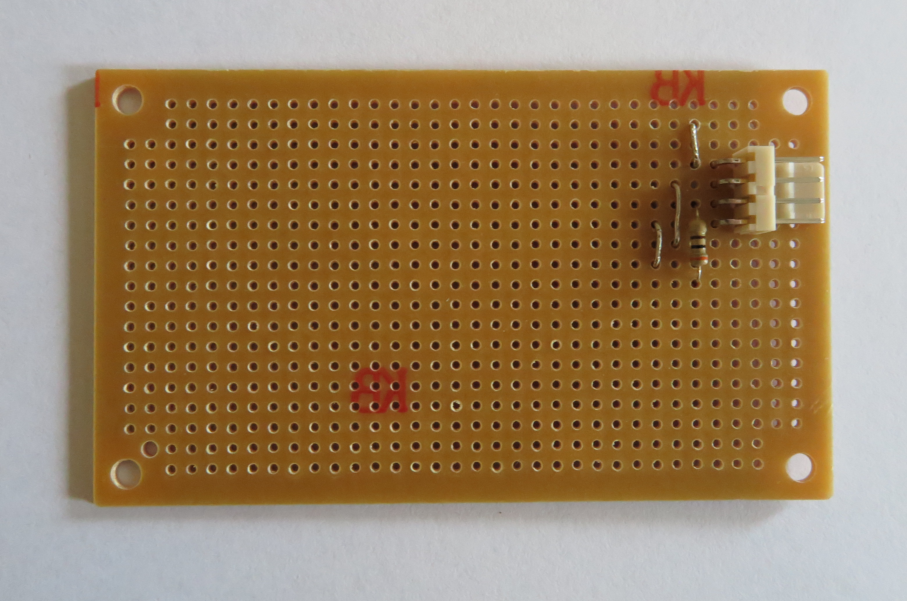
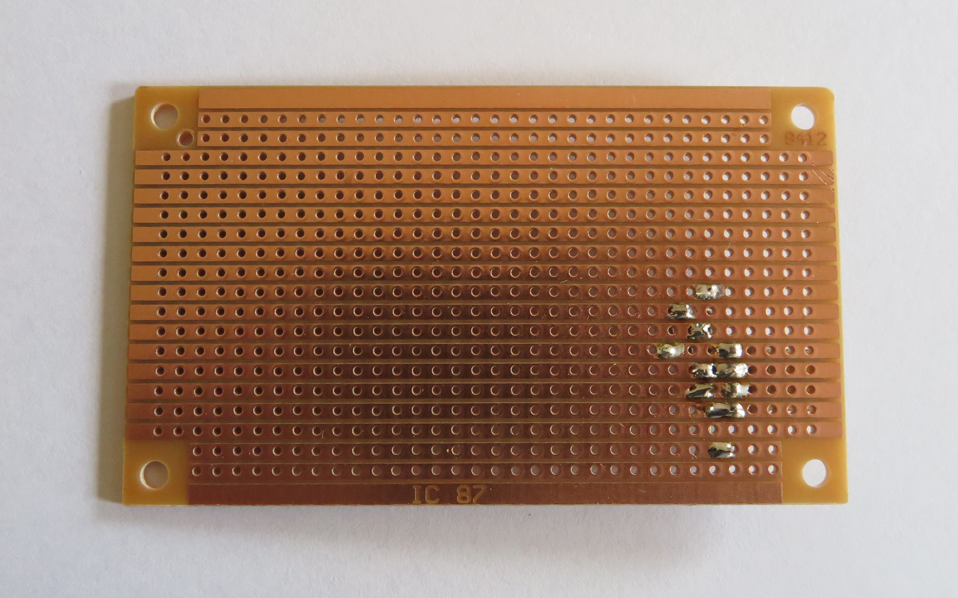
Each step in this process will include an updated hand drawn diagram that shows what it should look like AFTER adding the component described in the step. Then it will show a photo of the front of the circuit board with the new component in place. Finally it will show the board flipped over vertically to show the back of the circuit board with the solder connections. Note that flipping the board obviously flips the top and the bottom of the circuit visually. That means parts added to the top of the board will be at the bottom on this view.
The process of putting a part onto the board goes like this:
- Put the part on the front of the stripboard.
- Make sure it is in exactly the correct place (and facing the correct direction).
- Carefully flip the stripboard over, holding the part in place.
- Bend the leads of the part over so they are flush with the back of the stripboard in the direction that lines them up with the strip of copper that lines up with the hole they came through. (Some parts have very short leads, bending them is not required.)
- Solder the part in place.
- Trim the leads of the part to as short as you can without messing up the solder. (Don’t bother trimming leads on parts with very short leads.)
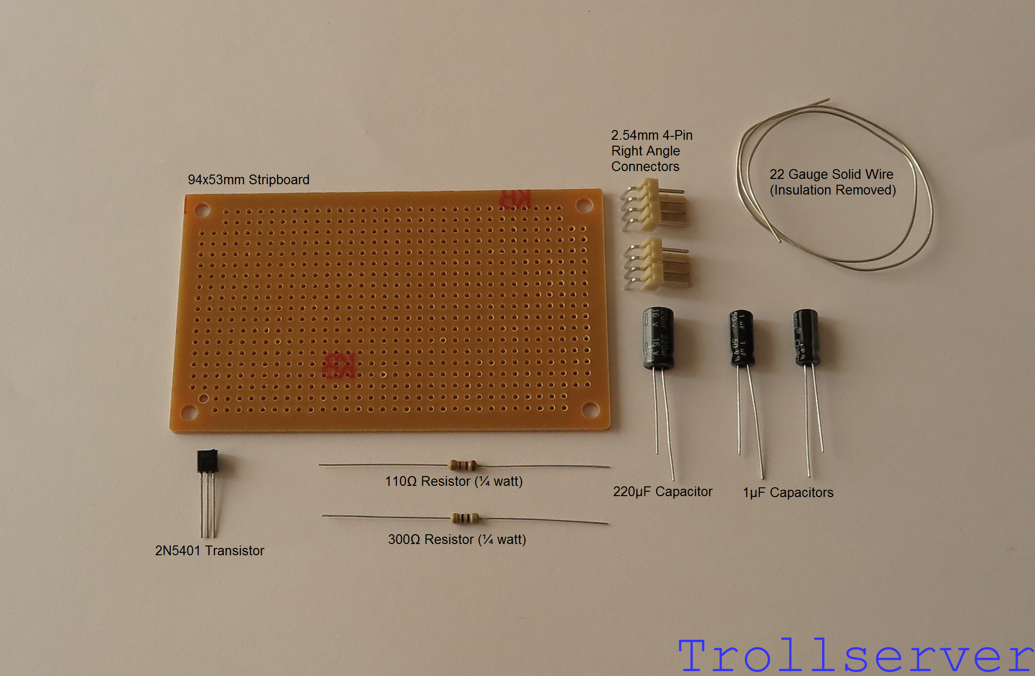
Here are all of the parts you’ll need to build the circuit board, shown in one picture with convenient labels.
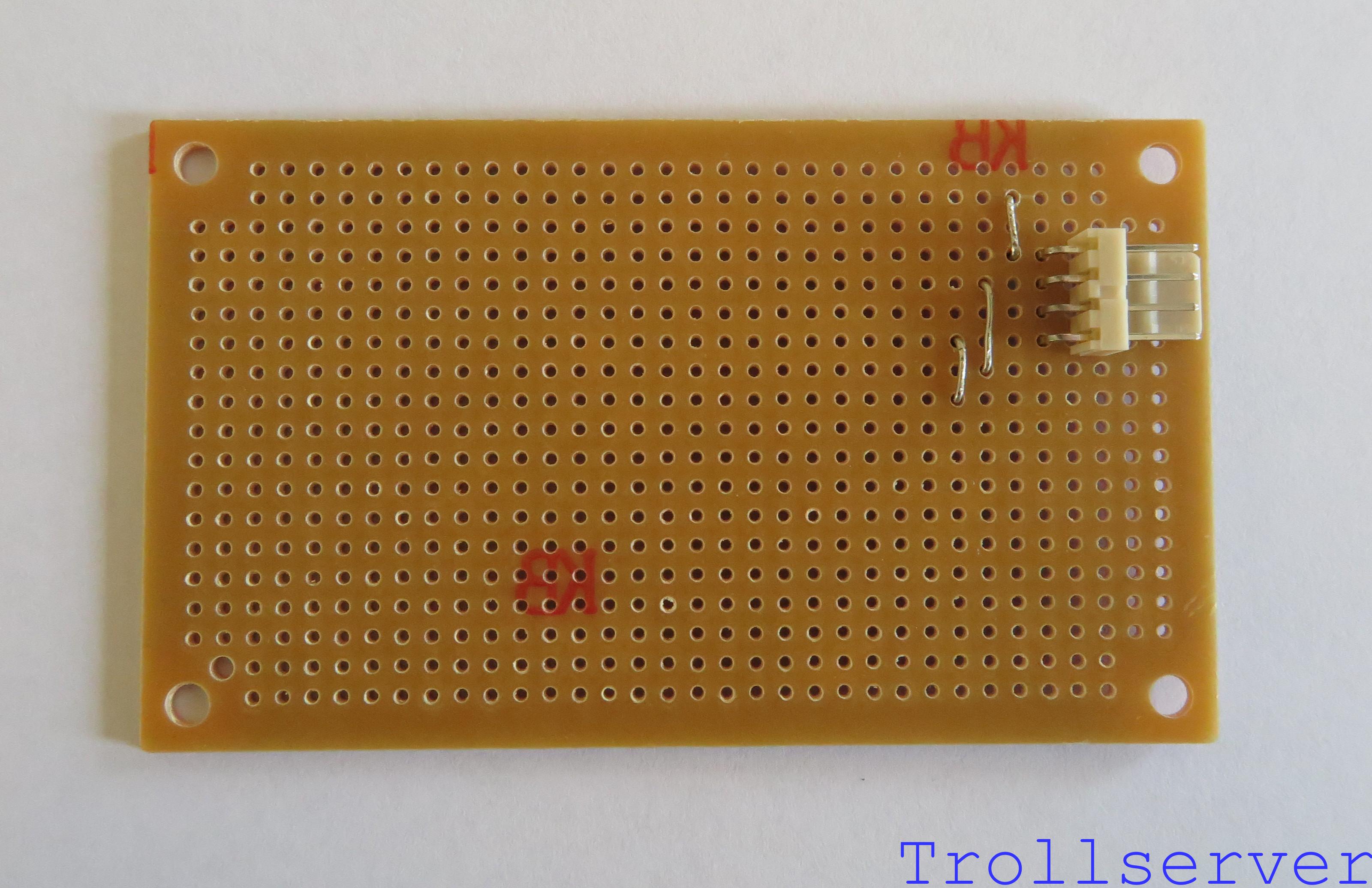
Step 1 – Input Connector
The first part to place on the board is the input connector. This is where the power, ground, audio, and video enter your circuit board from the NES motherboard. It has 4 leads that should be placed in 30-D, 30-E, 30-F, and 30-G. This component is placed where it is because we will need a little bit of room above the input connector for the audio half of the circuit and we are trying to support the entire plastic base of the connector with the stripboard.

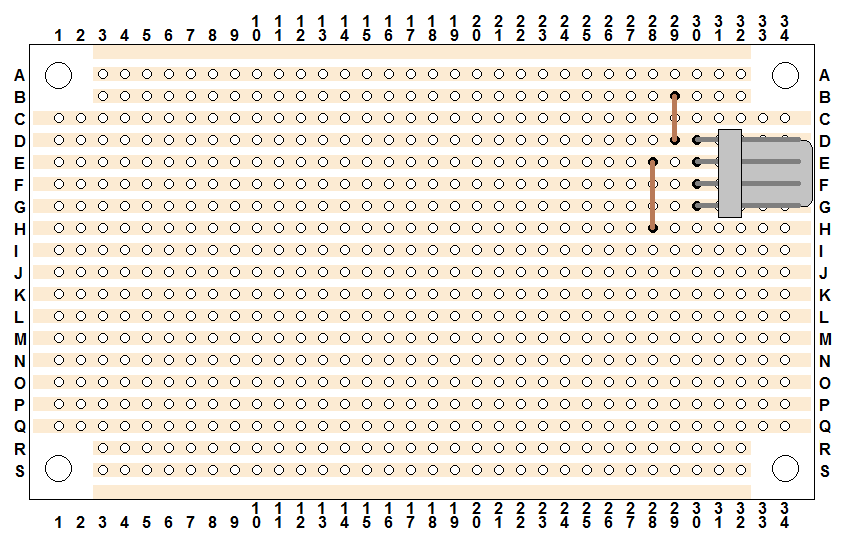
Step 2 – Audio Splitter
This “part” is actually just a piece of solid wire that has had the insulation taken off. You’ll need several of these as you build this board, so you can strip a reasonable length of wire now while you are working on this step. Don’t bother cutting it into short pieces either, it’s much easier to work with as a longer wire when you are weaving it in and out of the stripboard and you will be trimming the extra off after soldering it anyway. This wire goes down through holes 29-B and 29-D and serves the purpose of splitting the audio input into 2 “channels”.
The next couple of steps all involve stripped wire on the front of the circuit board. Be sure you make the wire tight and flush to the circuit board and that none of the wires touch each other. Since they aren’t insulated, that would obviously cause problems.
Step 3 – Transistor Ground
This is another piece of stripped copper wire. This time the wire goes through holes 28-E and 28-H and serves the purpose of providing ground to the transistor (which won’t be placed on the board for a while). Note that this is one column over to the left of the previous wire. Don’t put it directly below the other piece of wire because we need that space later.
Step 4 – Transistor Video Signal
This is another piece of stripped copper wire. This time the wire goes through holes 27-G and 27-I and serves the purpose of getting our weak input video signal to the transistor for amplification.
Step 5 – Transistor Power Resistor
This is the 300 Ω resistor (orange – black – brown – gold) and conveys the +5 volt input power to the transistor so the weak video signal can be amplified. I find it’s usually easier to work with resistor placement if you pre-bend the leads to 90 degrees. This gets them pointing in a direction that makes lining them up with the correct holes in the stripboard much easier. The resistor leads go through holes 29-F and 29-J.
Step 6 – Video Output Resistor
This time we’ll be using the 110 Ω resistor (brown – brown – brown – gold). Its purpose is to take the amplified and filtered video signal to the output connector for transmission to the TV. This resistor is crooked to save space and special care should be used to make sure you have it in the correct holes. It goes through holes 29-K and 32-L. This starts directly below the other resistor and the other side is only one row further down the board.
Head over to Part 2 to continue.
To jump between posts in this series, please visit the NES Mod Index.