NES Toploader AV Mod – RCA Output – Part 1
To jump between posts in this series, please visit the NES Mod Index.
Before we can add RCA jacks to the NES, there is a little bit of electrical work to do. By doing this first, we’ll conveniently have the things we will need later on. This particular process has a lot of steps, but they really shouldn’t take especially long to complete.
Start by cutting a piece of 4 Conductor wire that is about 15 inches long. Then split the 4 Conductor wire and strip all of the wires at both ends. I split one side of the wire farther than the other because the side that connects to the RCA jacks will benefit from a little bit of extra play. The side that goes into the 4 pin connector only needs to be long enough to get them into the connector without bending anything at weird angles. Continue by cutting 2 short pieces of wire (about 2″ each) and stripping the ends. Next, completely disassemble the RCA jacks and separate out the ground rings. You’ll eventually need all the parts, but for now you just need to not lose them since they aren’t involved yet. This is what you should have at this point.
Using the 2 short wires, and the black wire of the 4 conductor wire (from the end where you split it further) bend all three wires through the little hole in the tab of one of the RCA jack ground rings. Then do the same thing with the loose end of each short wire and the two remaining ground rings. The result of all this bending of wire should look like this when you are done.
If what you’ve created looks like what you see in the picture above then it’s time to solder it together. When that’s done, the more permanent version will look like this.
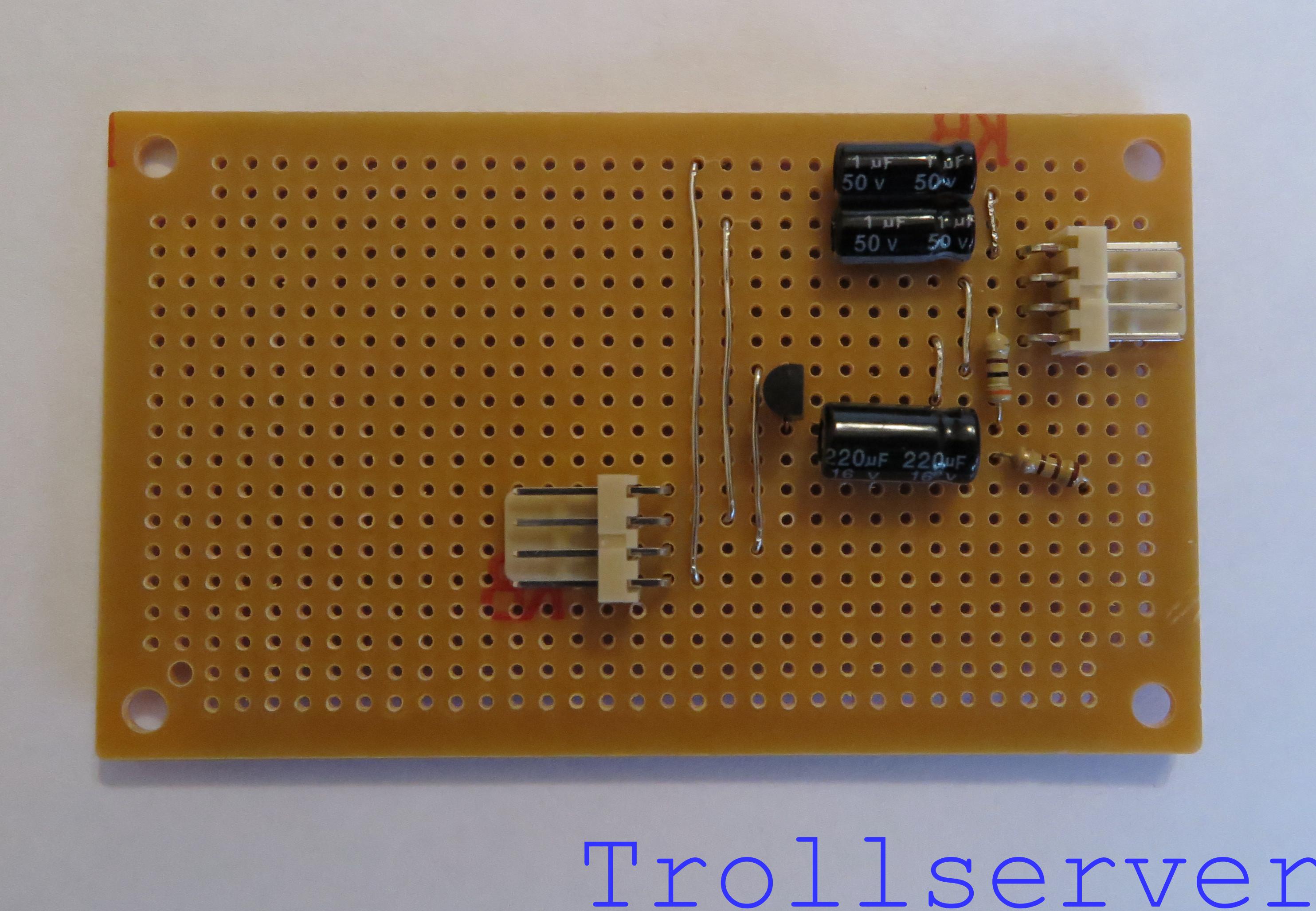
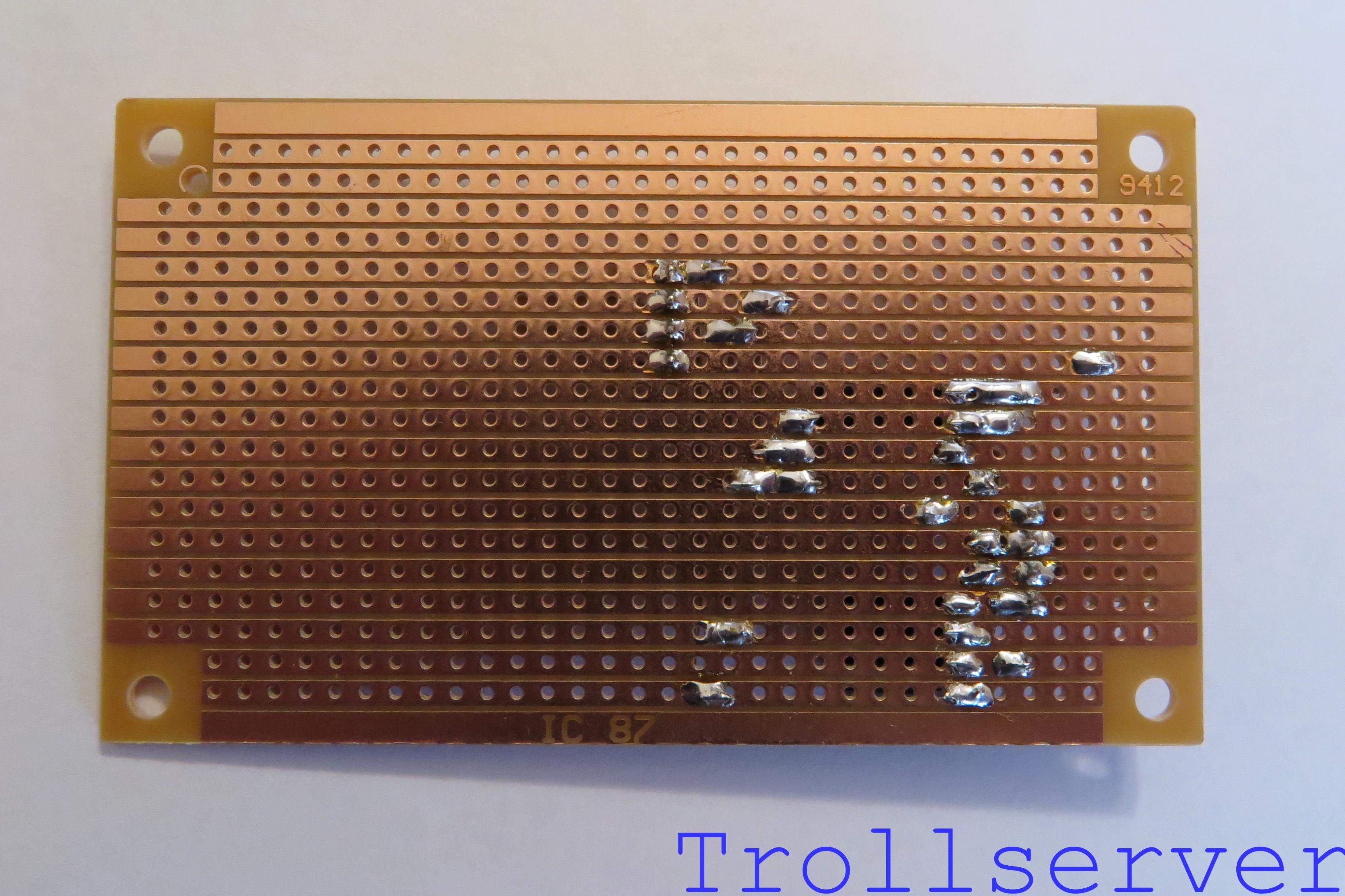
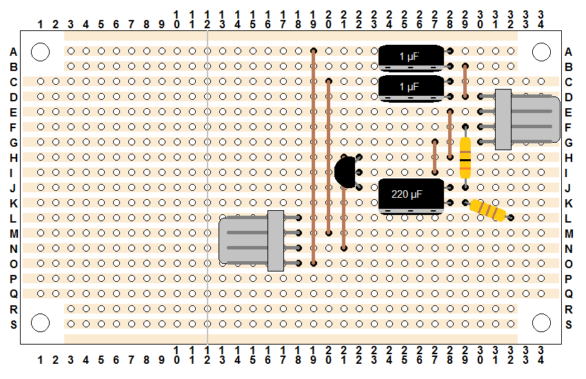
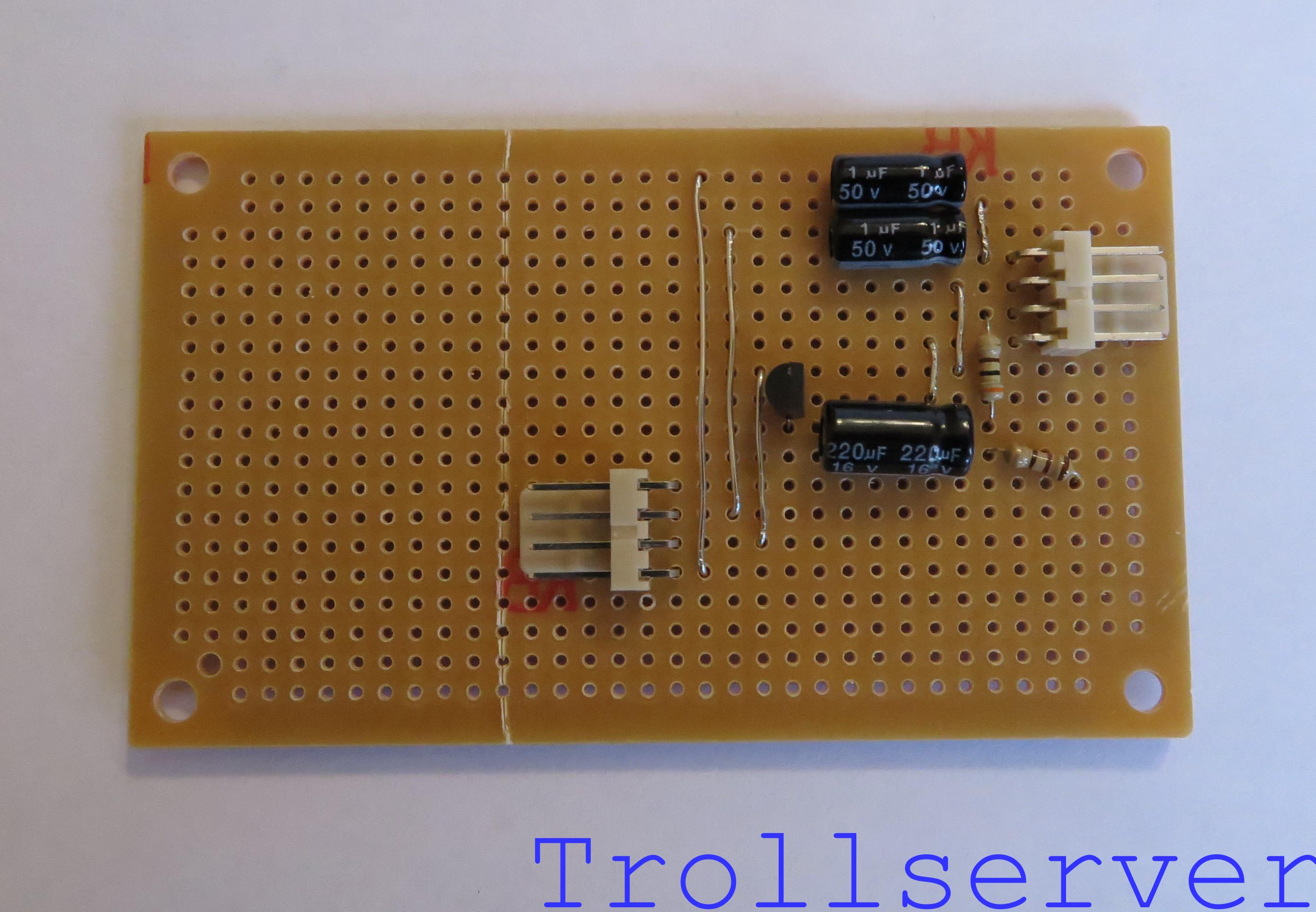
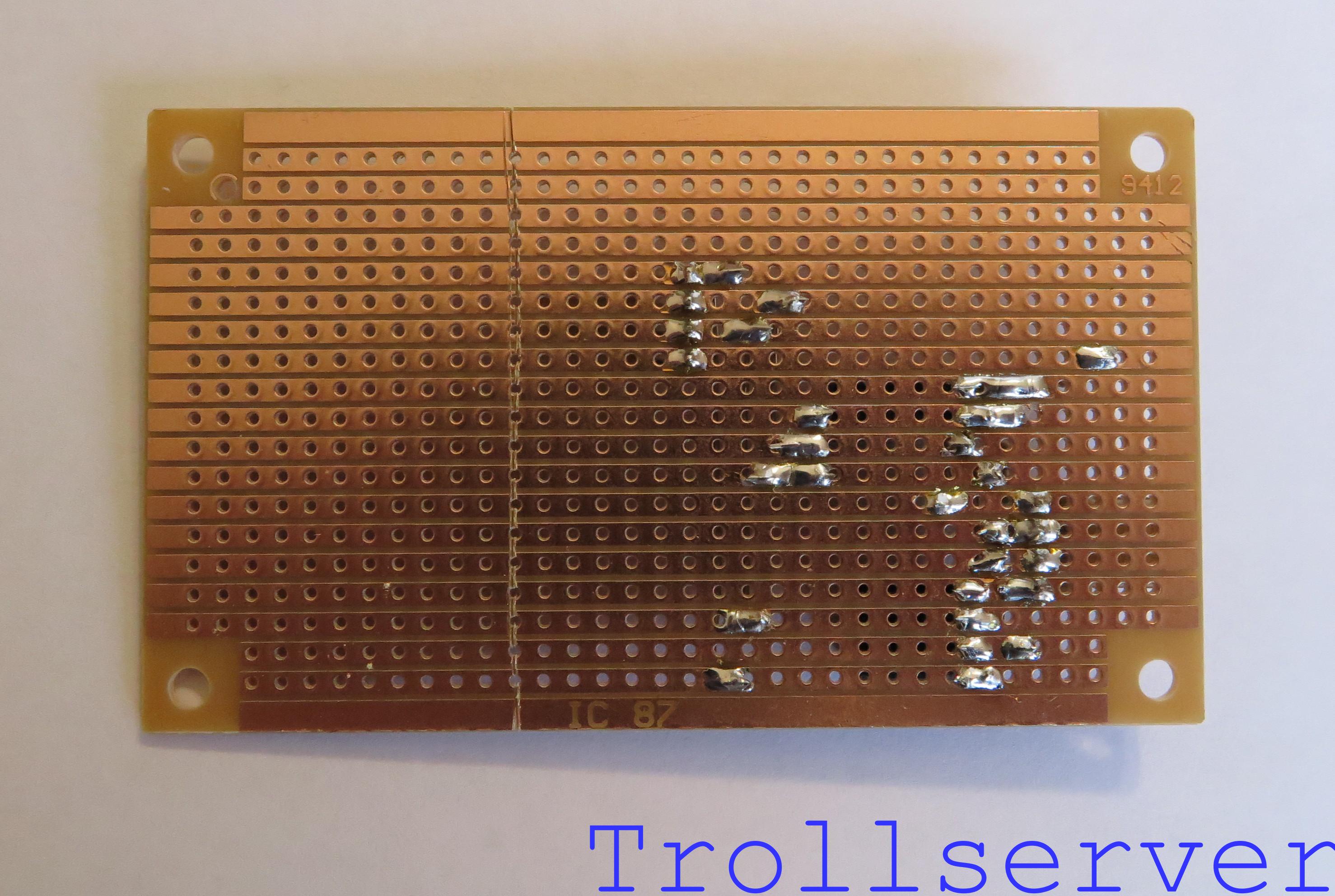
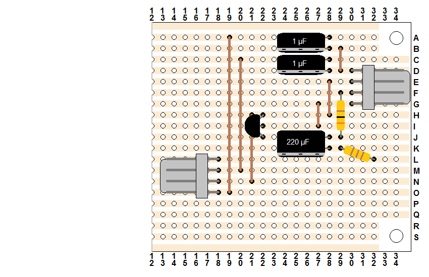
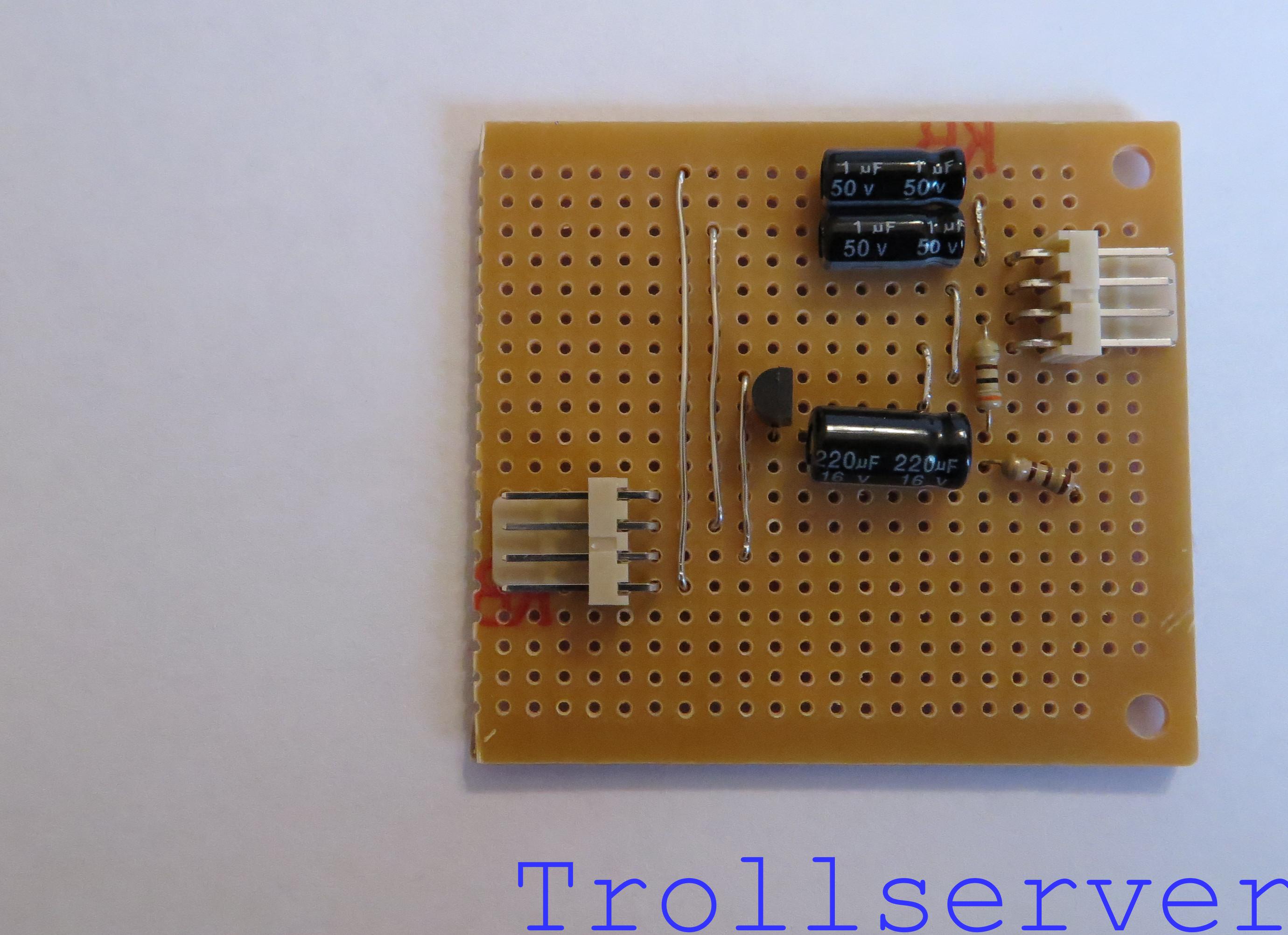
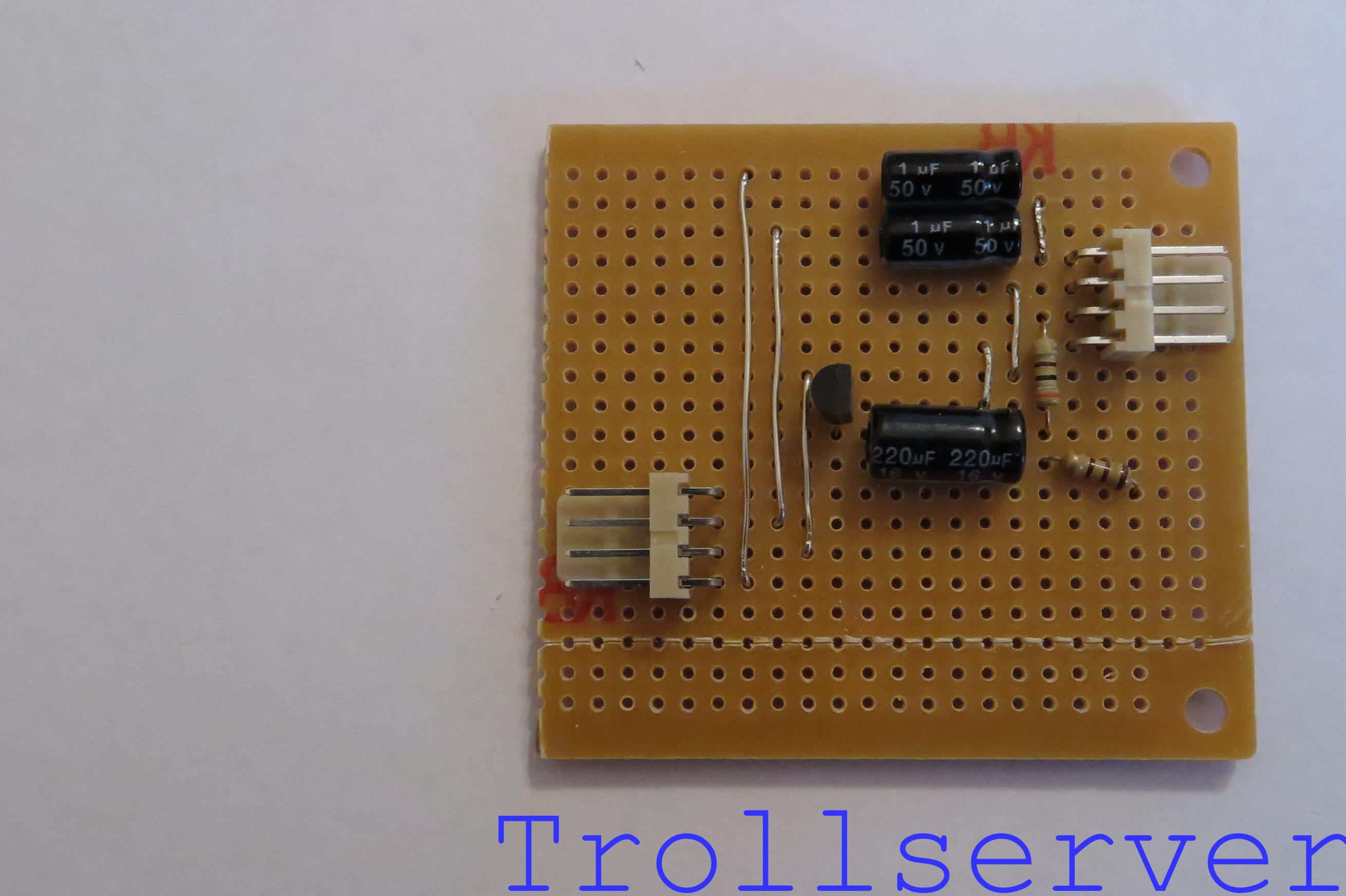
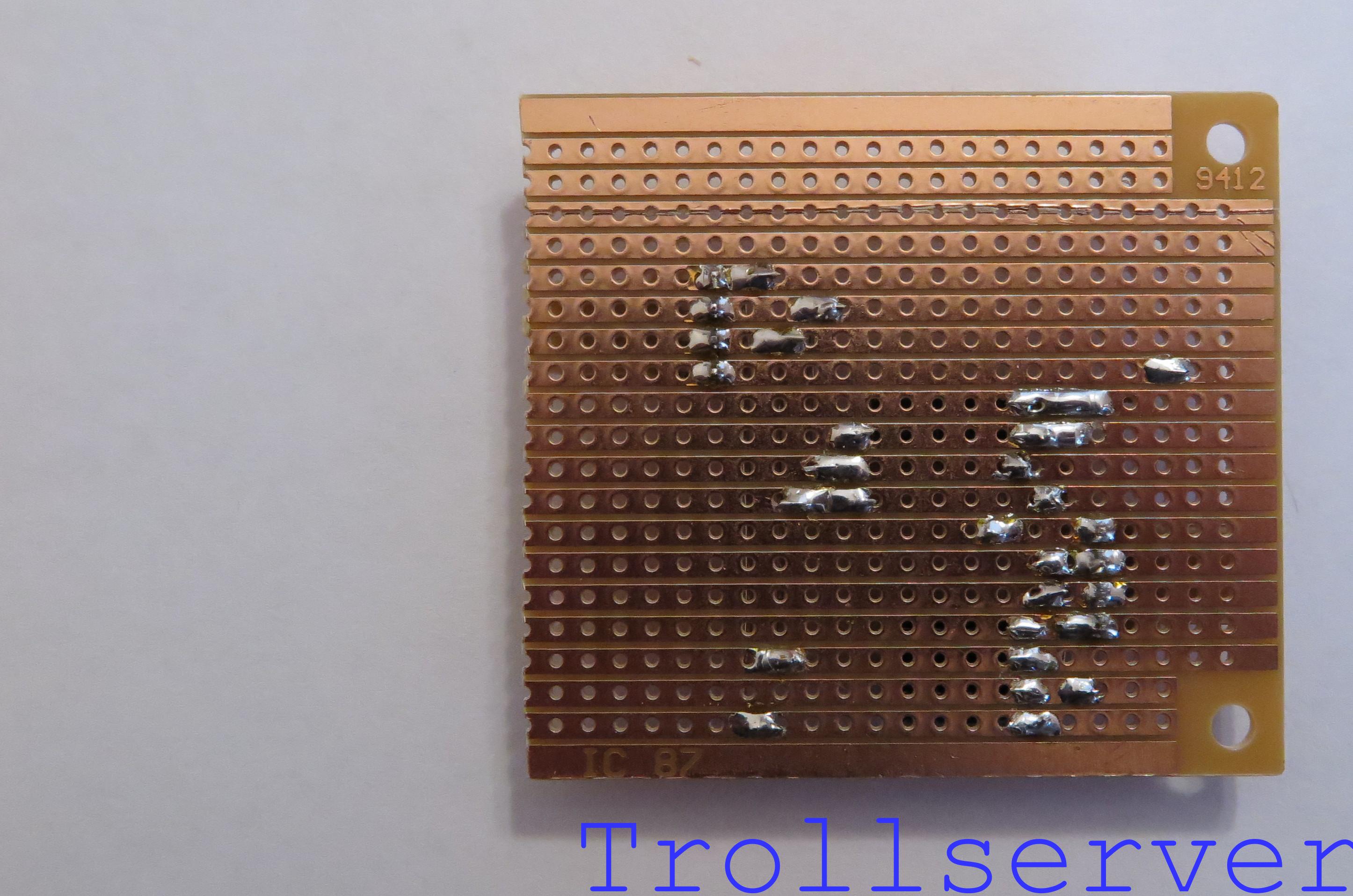
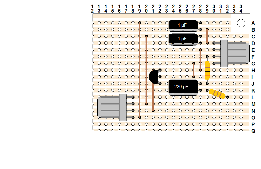
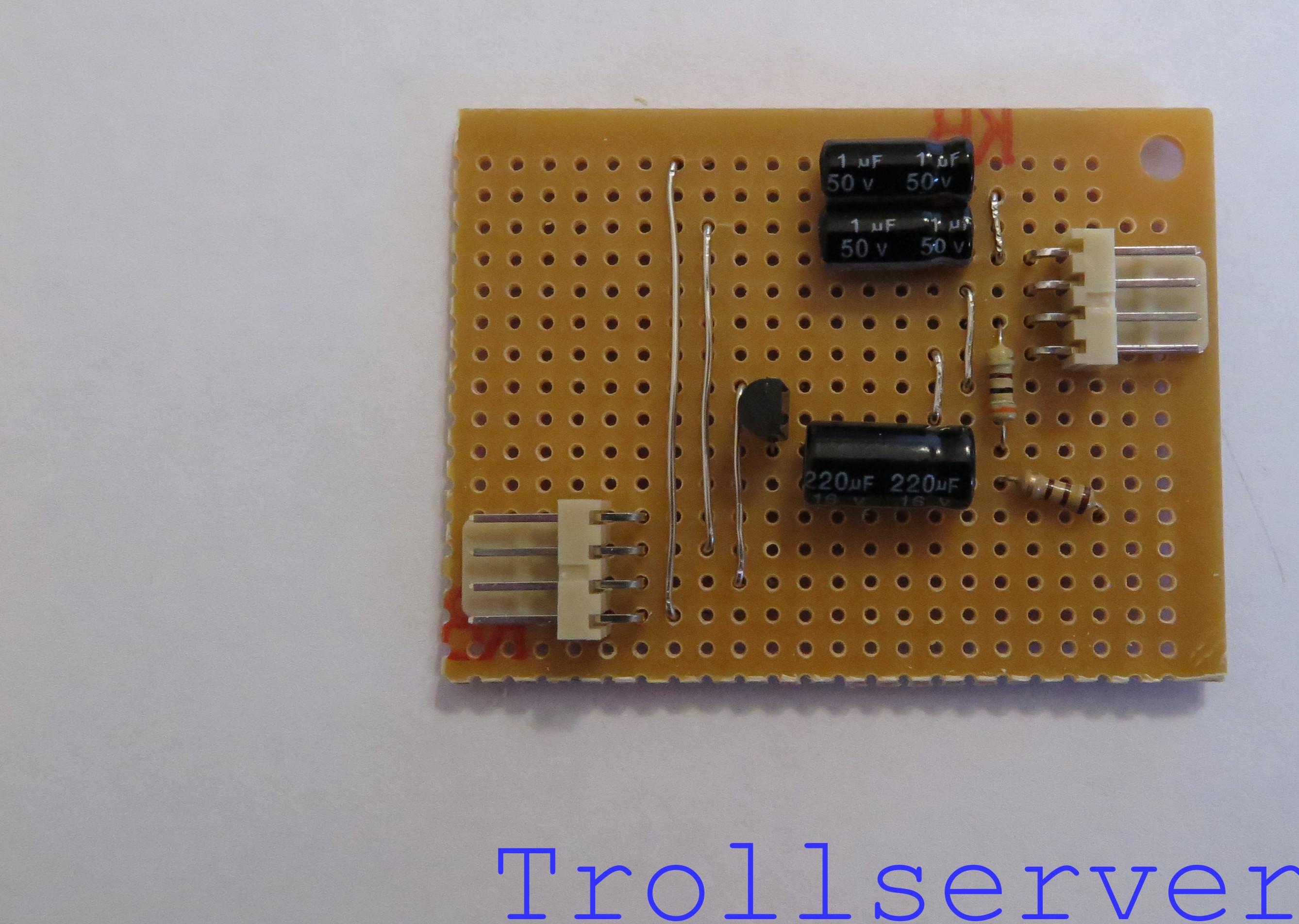
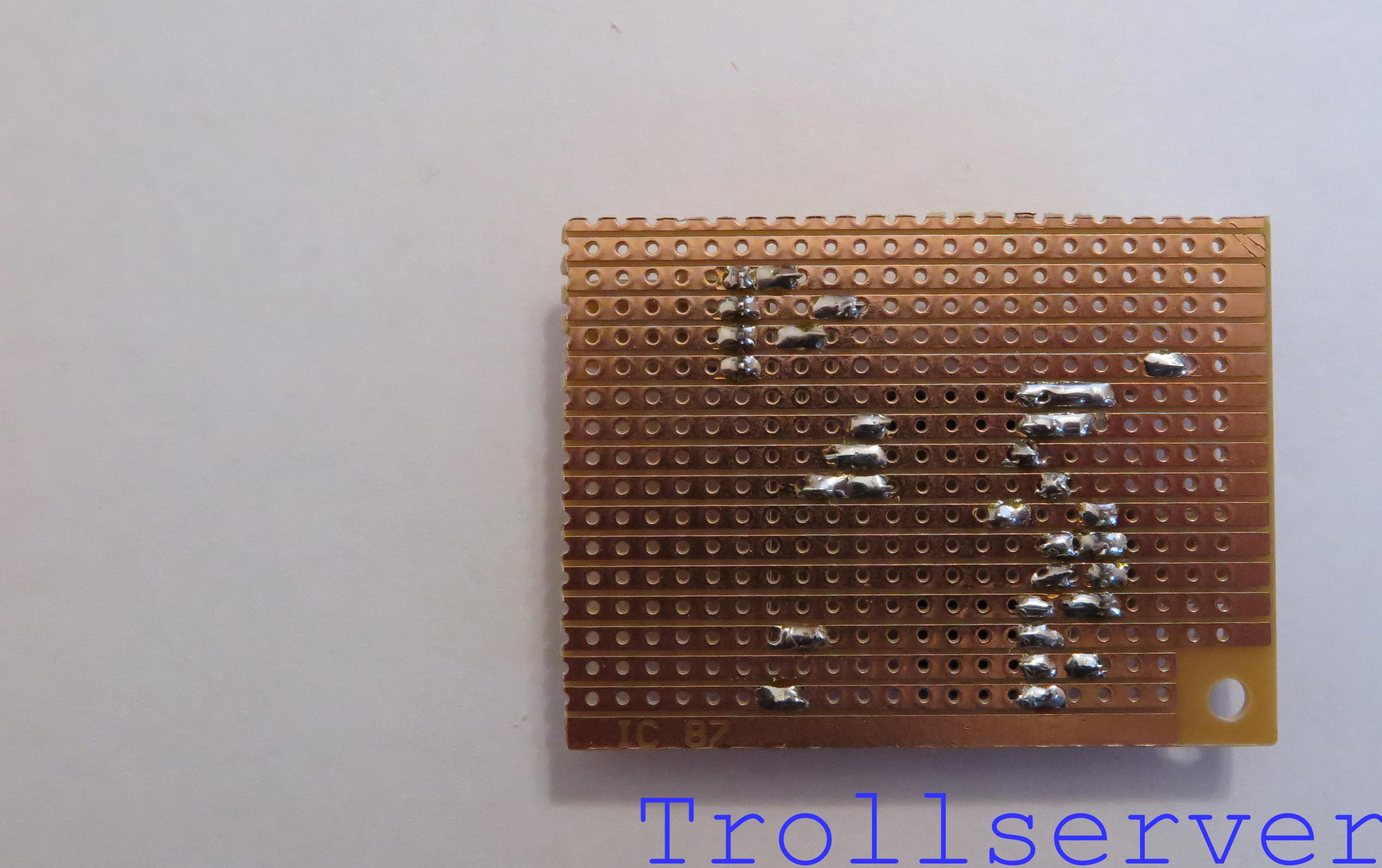
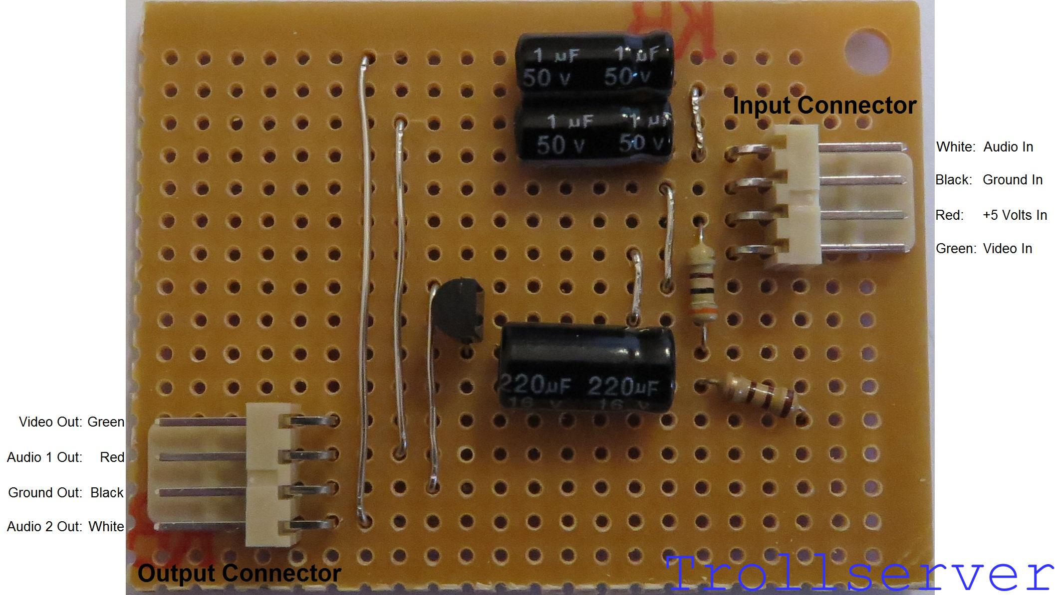
Next we need to build the 4 Pin Connector that will hook the RCA Jacks to the output side of the circuit we built. The connectors are quite small and lining them up to solder them is a little bit of a pain but the trickiest part here is to make absolutely sure your pins are in the correct order. To assist in this, here is a labeled version of the circuit board we built. Note that the output is on the lower left and the input is on the upper right. Also note that the input and output color order are the opposite of each other. If you mark each connector with a smudge of black where the ground pin is then each wire you connect to the board will only go on the correct connector where the black wire lines up with the black smudge. I also usually write “IN” and “OUT” on the board and the connectors with a marker just so it’s super clear.
The 4 pin connectors are a bit tricky to assemble, and you need to make sure you are doing it correctly. I’ve personally assembled them backwards and then been surprised at myself. “How the heck did I do that?” The answer is that there are a lot of spacial reasoning problems involved and you only need to get one of them out of whack to end up with something wrong. To help keep you from doing something wrong like I have in the past, I have a list of pointers that might help you.
- The connector shell (the thing that connects to the picture above) has 2 plastic fins on the bottom of the connector. They go around the plastic foot below the 4 pins of the connector shown above. (Don’t get it upside down.)
- The connector shell has large holes on one side and small holes on the other. The small holes are the ones that the 4 pins of the connector shown above go into. The large ones are where the actual wires come out. (Don’t get it backwards.)
- The connector shell has 4 little rectangle holes on the top. The connector pins have tiny metal flaps on one side. The little flaps lock into the rectangle holes. (Don’t get the pin parts upside down.)
- When soldering to the connector pins, because of how the pins face when you lay a wire into them from the top, you will be making them upside down! Remember this when it comes to ordering the wires the right way. (Don’t plan your wires backwards.)
Before you panic about how complex all this is, I will now attempt to show you how to do all of the above correctly. Start by breaking the connector pins off of their structural rib. You should just be able to bend them back and forth a couple times and they’ll snap off. We’ll be building the connector with the side of the 4 conductor wire that was separated shorter than the other. (And that obviously doesn’t already have RCA jack ground rings soldered to it.)
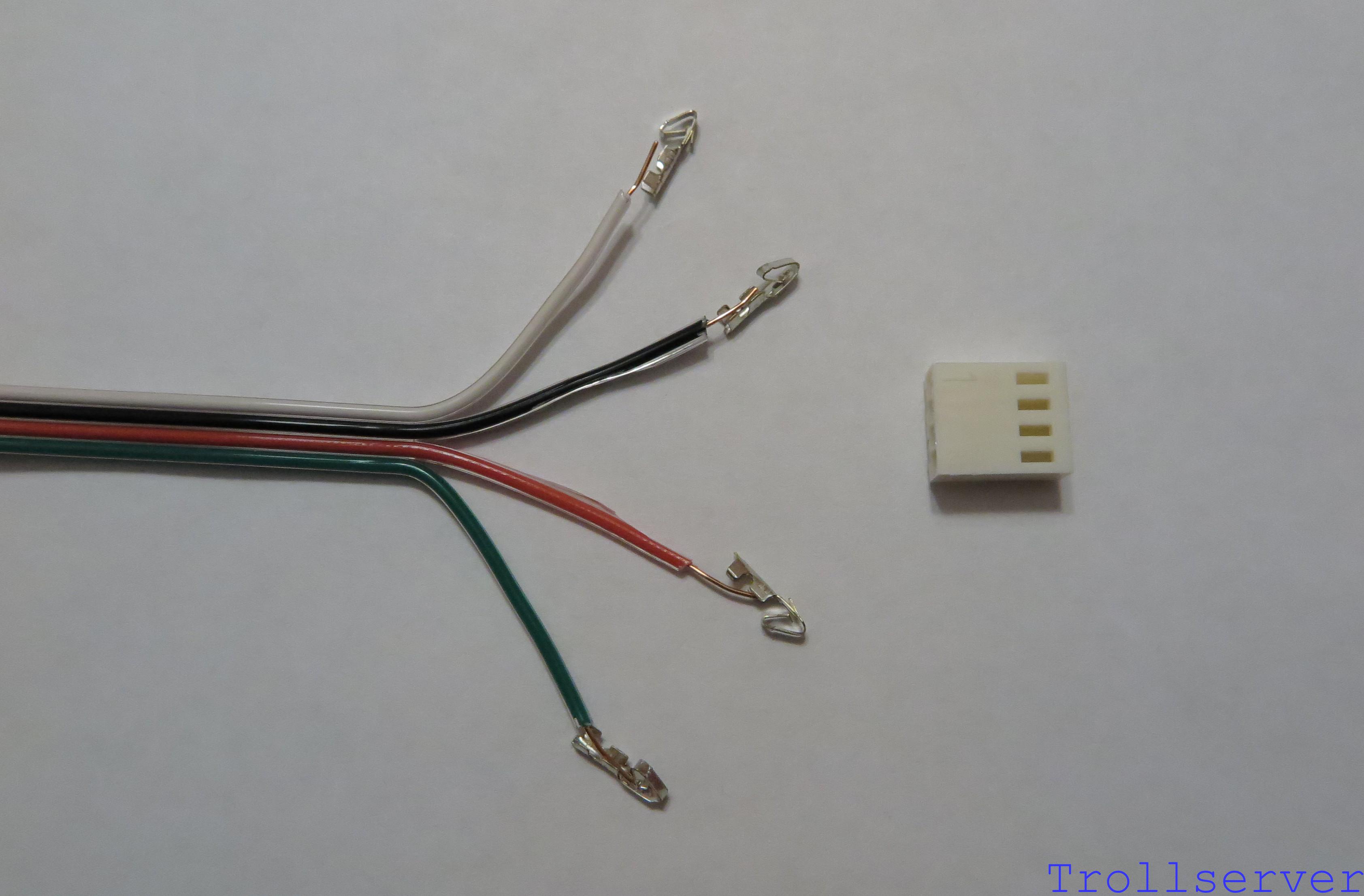
The output pins, from top to bottom are Green, Red, Black, then White. Because of all the fun gotchas listed above that means we actually need to start with our wire in the opposite direction. Layout the wire with the colors White, Black, Red, then Green from top to bottom as shown below. The connector pins shown in the picture below aren’t attached to anything yet.
I’m extremely anal when it comes to attaching the connector pins to their respective wires. Technically you can lay out the wire and simply crush the crimp flaps around the wire. To me, that’s just begging for electrical connection problems down the line. I actually solder them in place (be careful to not use a lot of solder or it won’t fit in the connector shell), then I use both sets of crimp flaps. In other words, it actually takes me longer to build the input and output connectors than it does to build the circuit board. I’m not going to tell you to do it the way I do, but I’ve never had a connector go weird on me after years and years of service, so you probably should. 🙂
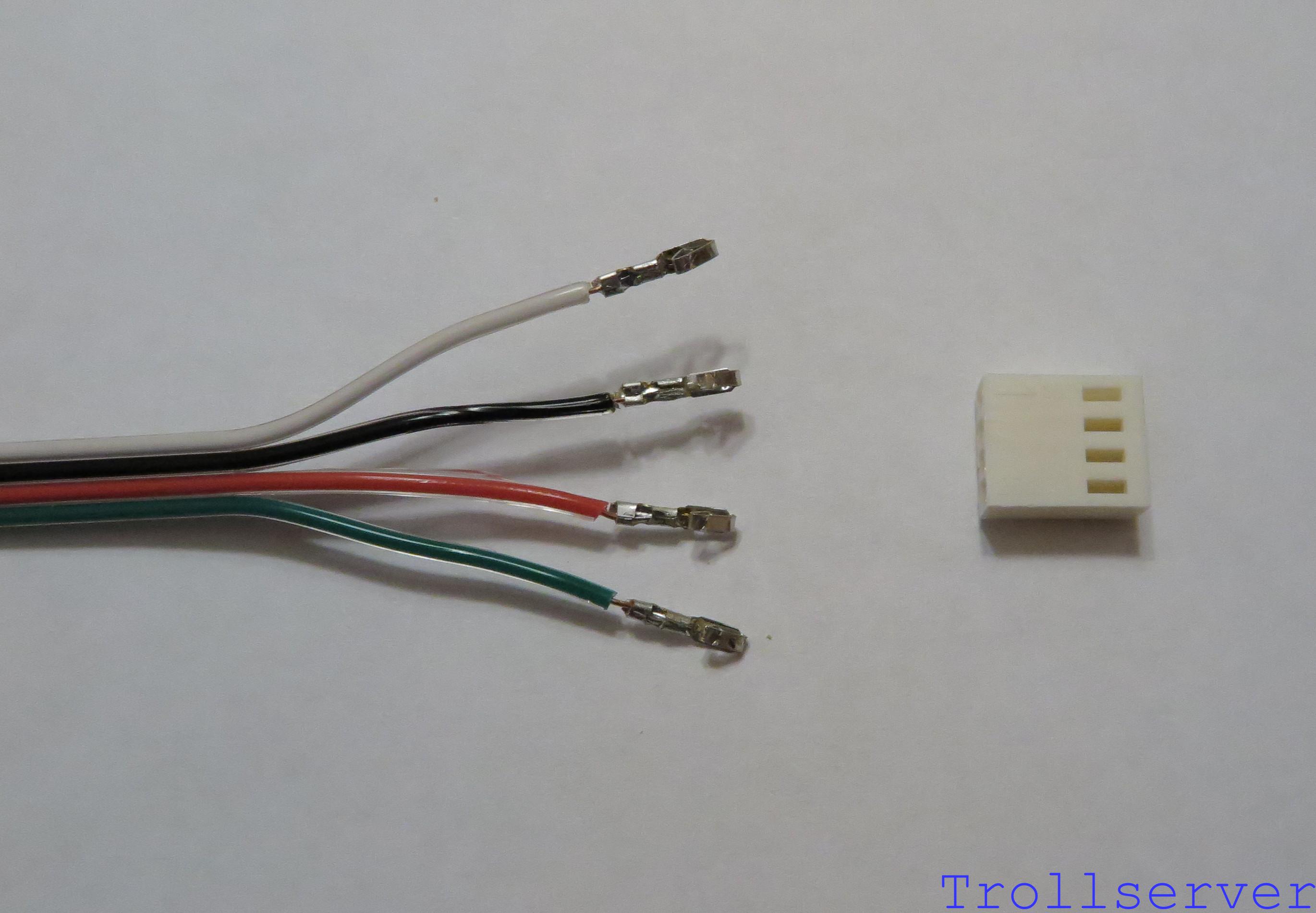
This is what it looks like after I’ve soldered all my connections and crushed all my crimp flaps in place. Don’t forget that this is upside down still, so to assemble the connector we need to flip the whole wire over first.
This is what the finished connector looks like. To build this, after you flip the wire over, simply insert the connector pins into the connector shell one at a time. Be sure each of the little locking tabs click into place in the small rectangle holes.
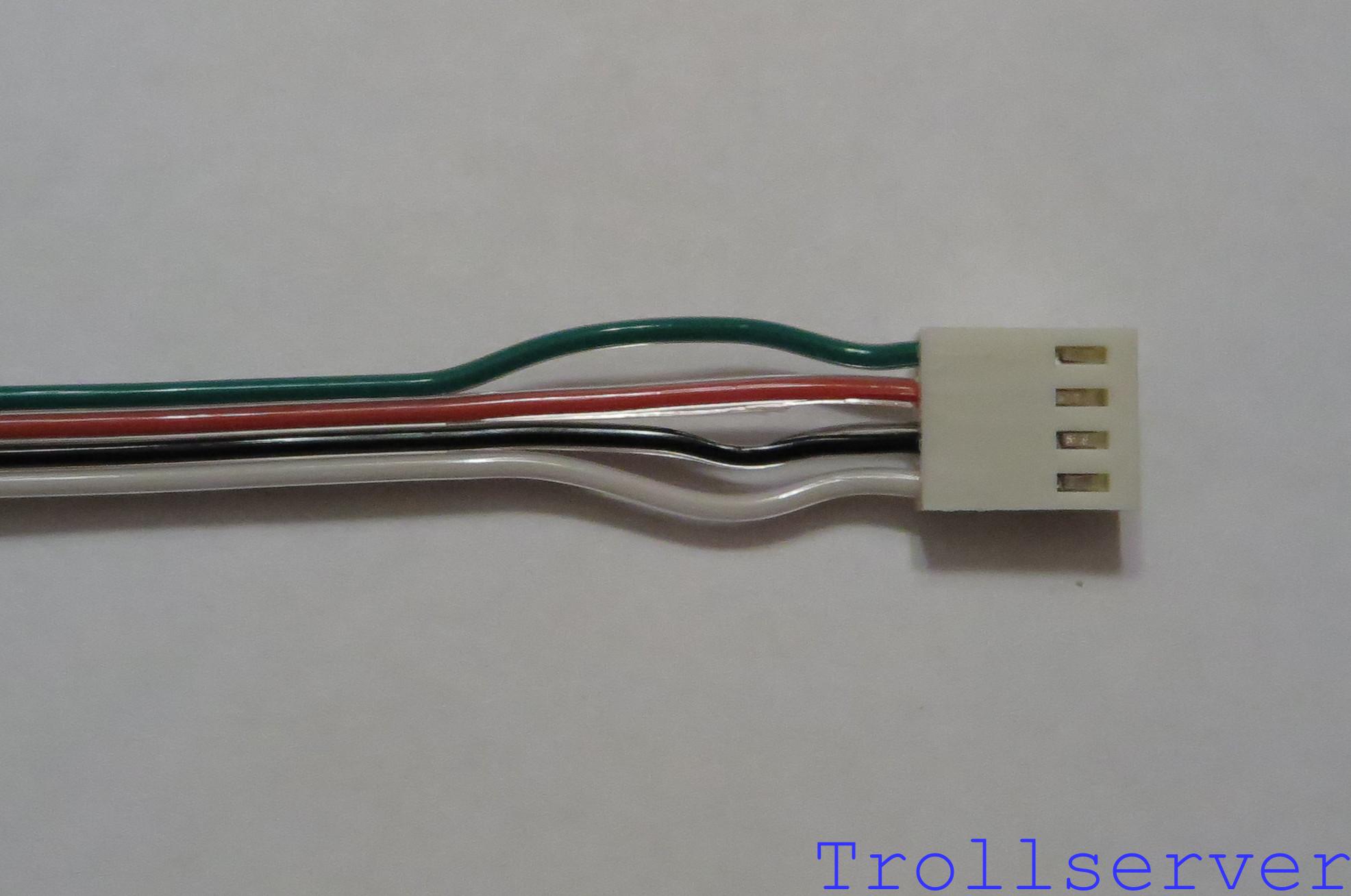
You should now have a nice piece of wire ready to attach to both the circuit board and the RCA jacks.
Head over to Part 2 to continue.
To jump between posts in this series, please visit the NES Mod Index.