Category Archives: Electronics

NES Toploader AV Mod – Motherboard Input – Part 2

To jump between posts in this series, please visit the NES Mod Index.


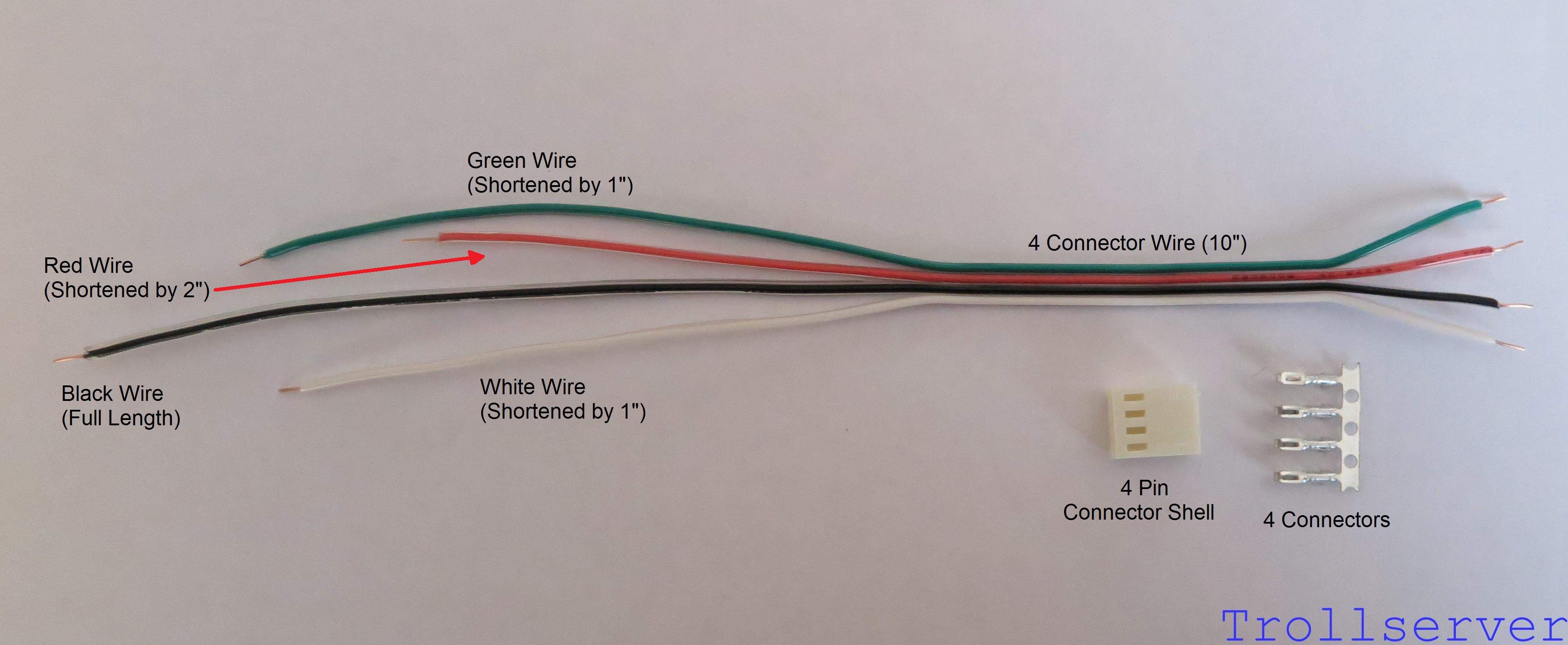
This is the second part of the instructions for connecting your circuit board to the motherboard in your NES.  This part involves the scariest bits of the whole process.  If you haven’t already created the input wire you should head back to Part 1 for instructions.

One part of this process is optional, but I HIGHLY recommend doing it even if you are scared about it.  The difference in output quality is so much better that I can’t really recommend not doing it.  I will attempt to make the optional step obvious and to take enough pictures to be helpful but I will be doing the optional step so I won’t be able to provide any pictures of what it looks like if you skipped it.

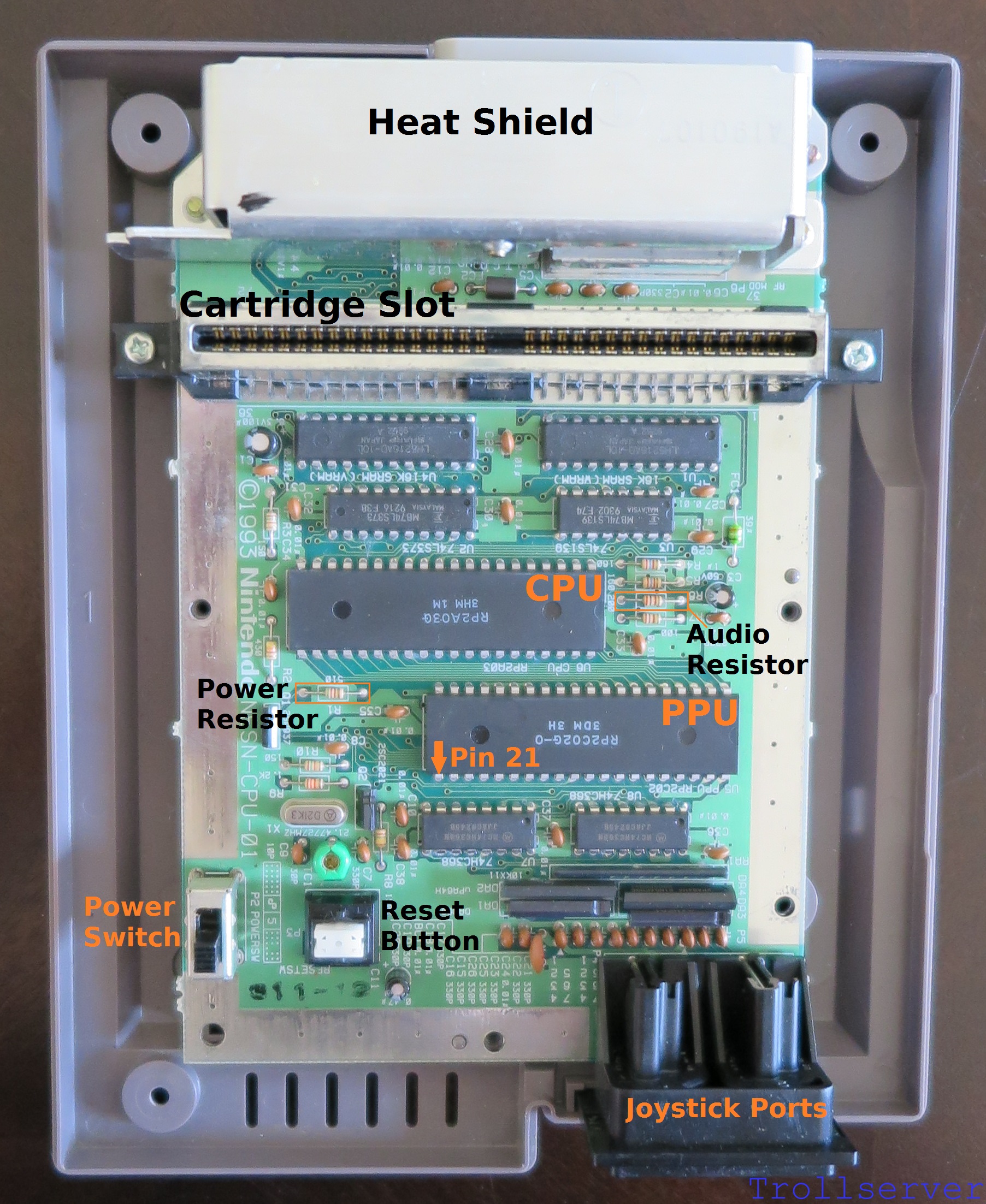
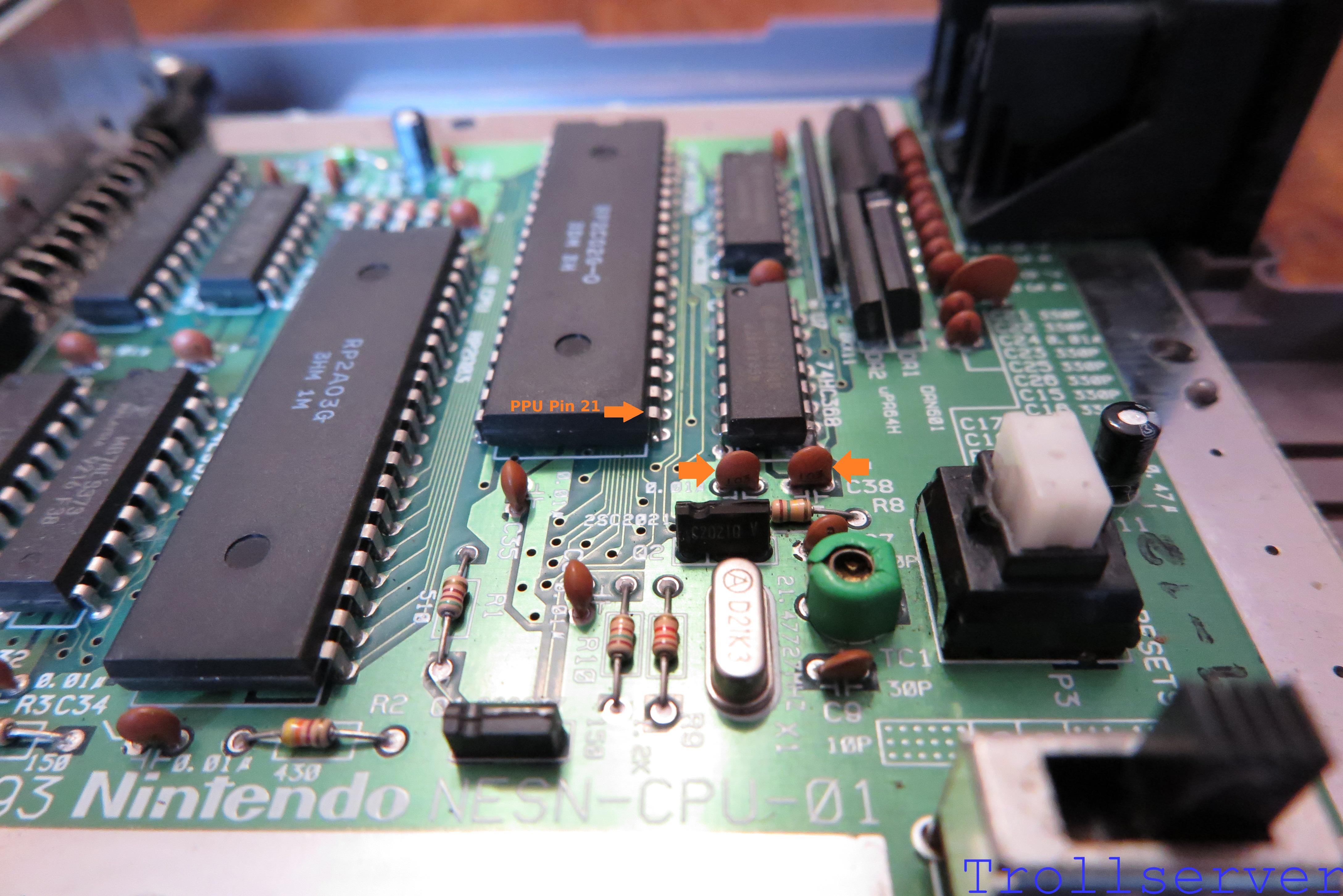
First a little bit of NES motherboard geography.  This will make talking about things a little easier later on.  To assist with geography there is nothing better than a proper map with convenient labels.  I’ve gone with orange or black labels depending on the background color so they stand out nicely.  Here is our NES motherboard reference map.  (Don’t forget most of the pictures on this site are clickable to see vastly larger versions.)

nes_mother5board_reference_map_version2


Step 1 – Connect the Audio Input Wire

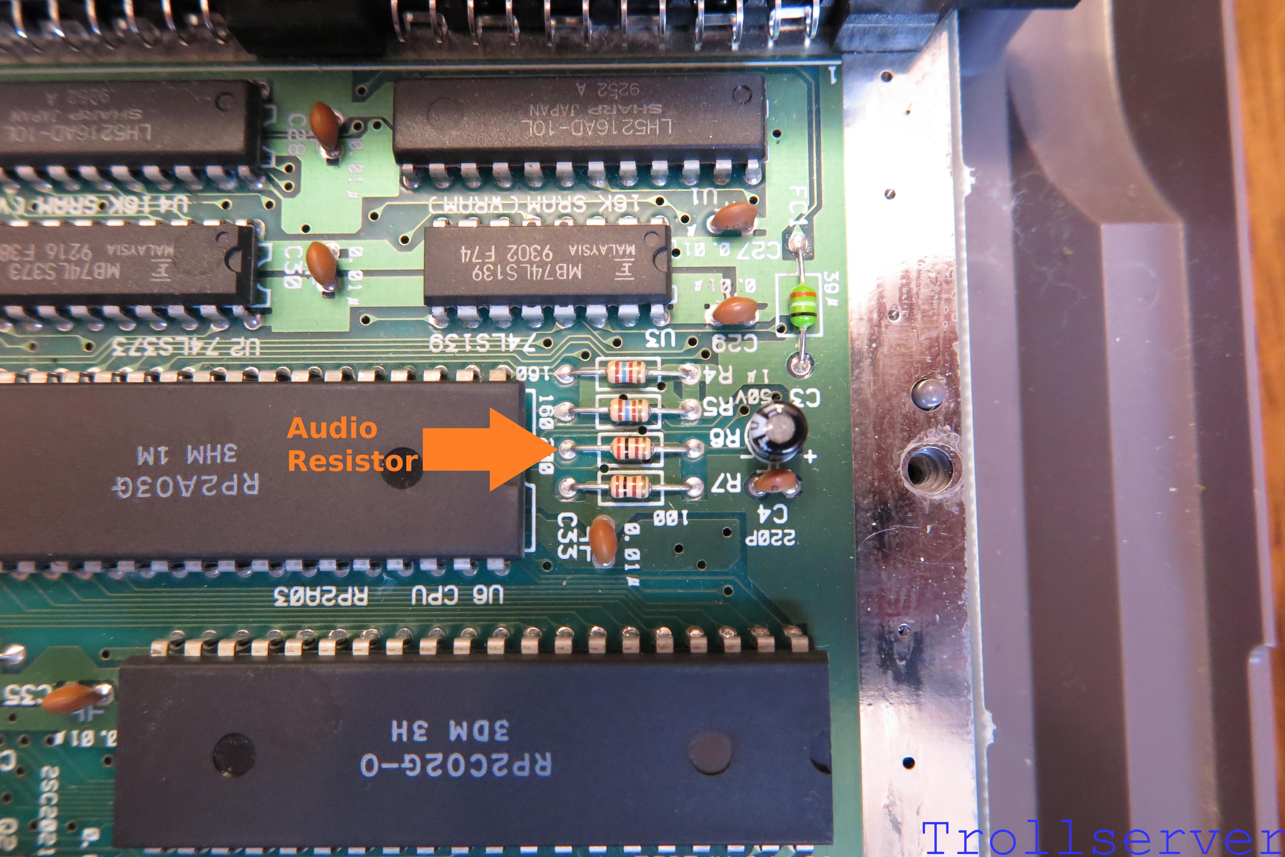
The first thing to wire is the audio.  To the right of the CPU is a bank of four resistors labeled R4, R5, R6 and R7.  The audio comes out of the CPU and heads through R6.  We want the audio directly out of the CPU so we need to solder our white audio wire to the R6 resistor leg that’s on the side toward the CPU (before the signal goes through the resistor).

audio_resistor

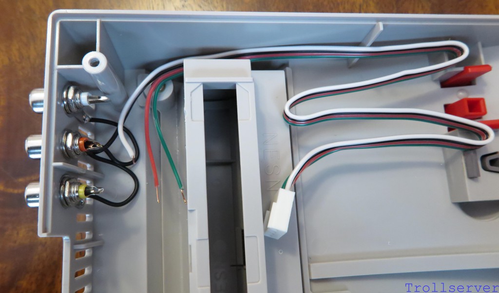
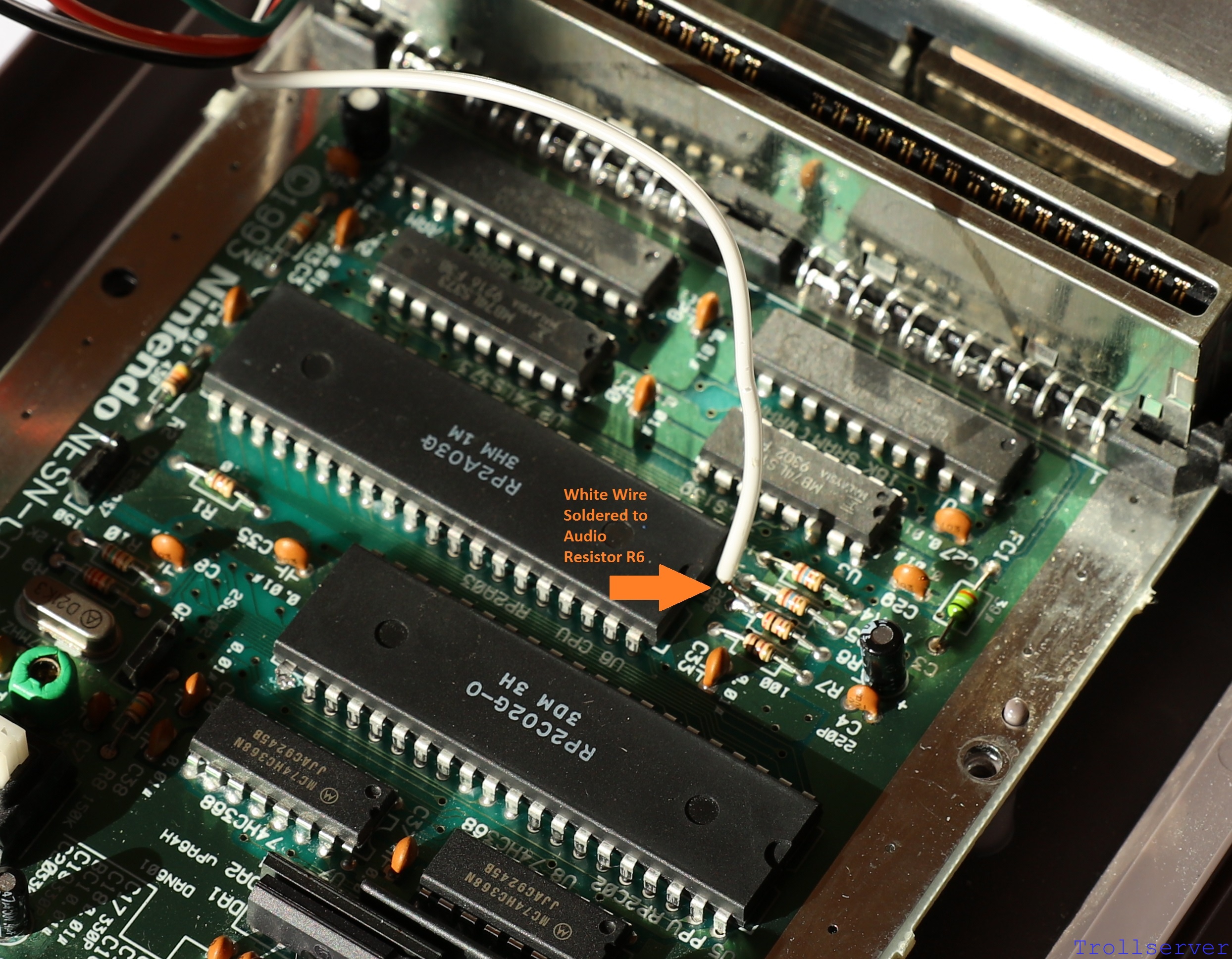
After soldering the White Audio Input Wire to the side of Audio Resistor R6 that is closer to the CPU it should look a bit like this.

motherboard_input06


Step 2 – Connect the +5V Power Wire

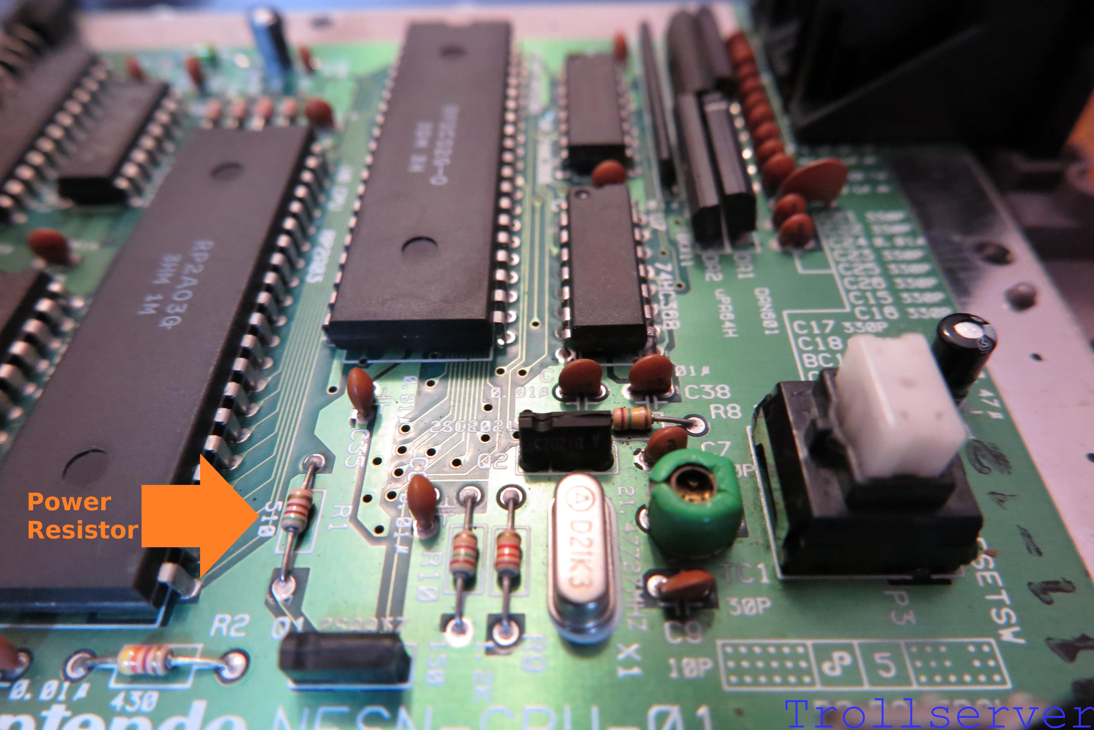
We need some +5V power so we can amplify our video signal before we send it out to the TV.  We get that from the resistor on the left side of the CPU labeled R1.  In this case we want the power after it has gone through this resistor on its way into the rest of the system.  That means we need to solder our red power wire to the R1 resistor leg that’s on the side toward the PPU.

power_resistor_r1

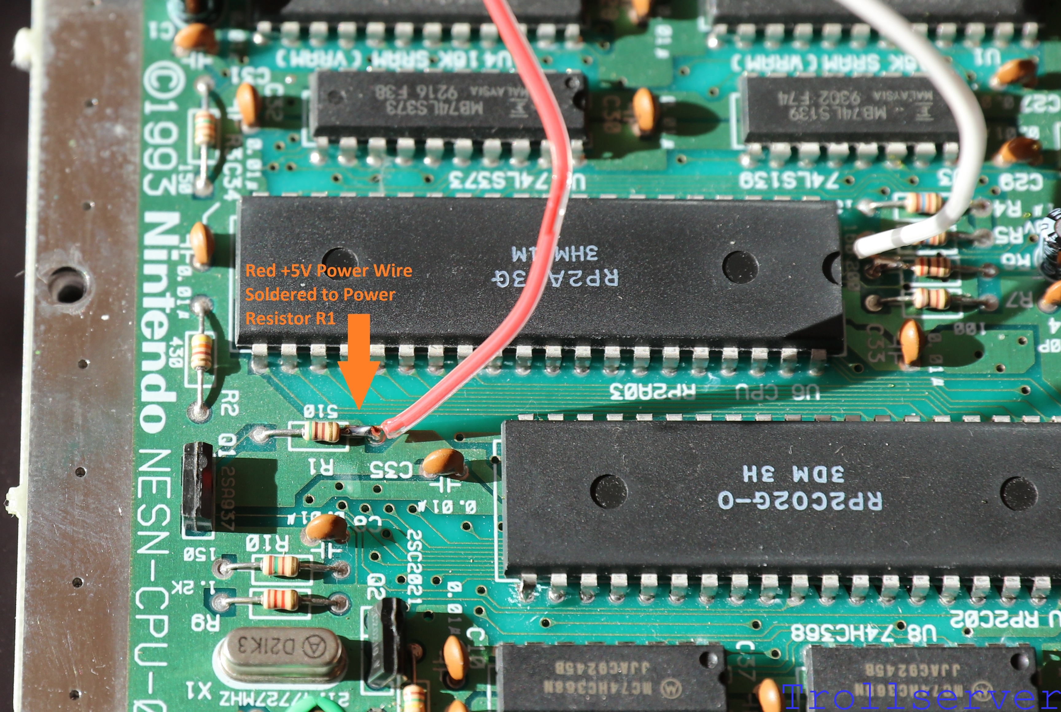
After soldering the Red +5V Power Wire to the side of Power Resistor R1 that is closer to the PPU it should look a bit like this.

motherboard_input07


Step 3 – Disconnect PPU Pin 21 from the Motherboard

This is the optional step!  If cutting and bending the pin of a chip is too scary then skip this step and proceed to step 4 but understand that your video output quality will not be much improved over just using an unmodified toploader.

Pros

  • Your video quality will be so much better it’s almost ridiculous.
  • Isn’t better video quality sort of the whole point of this operation?
Cons

  • If something goes wrong your NES may literally be garbage.
  • You are cutting and bending a pin on a 25 year old chip.
  • You have an extra step to do during this process.  (This step in fact.)

Ok, now that you have been sufficiently warned about the potential of accidentally destroying your NES and you’ve been given the chance to skip this step, it’s time to plow ahead assuming you are going for it.  Let’s do this.  🙂

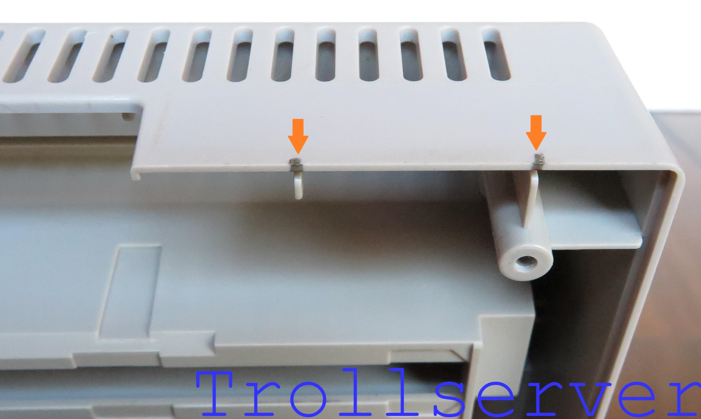
Ok, I lied.  One more quick warning here, when cutting the pin be super attentive to the capacitors that are right near where you are working.  (Shown with arrows in the image below.)  I’ve broken one of them accidentally and it’s a pain to replace.  Be especially careful with the capacitor on the left in the picture below.  When I broke it I did so by pressing on it accidentally with the handle of the tool I was using to cut the pin.  It snapped in half and I didn’t even notice until I was putting things back together, so just be careful.

ppu_nearby_capacitors

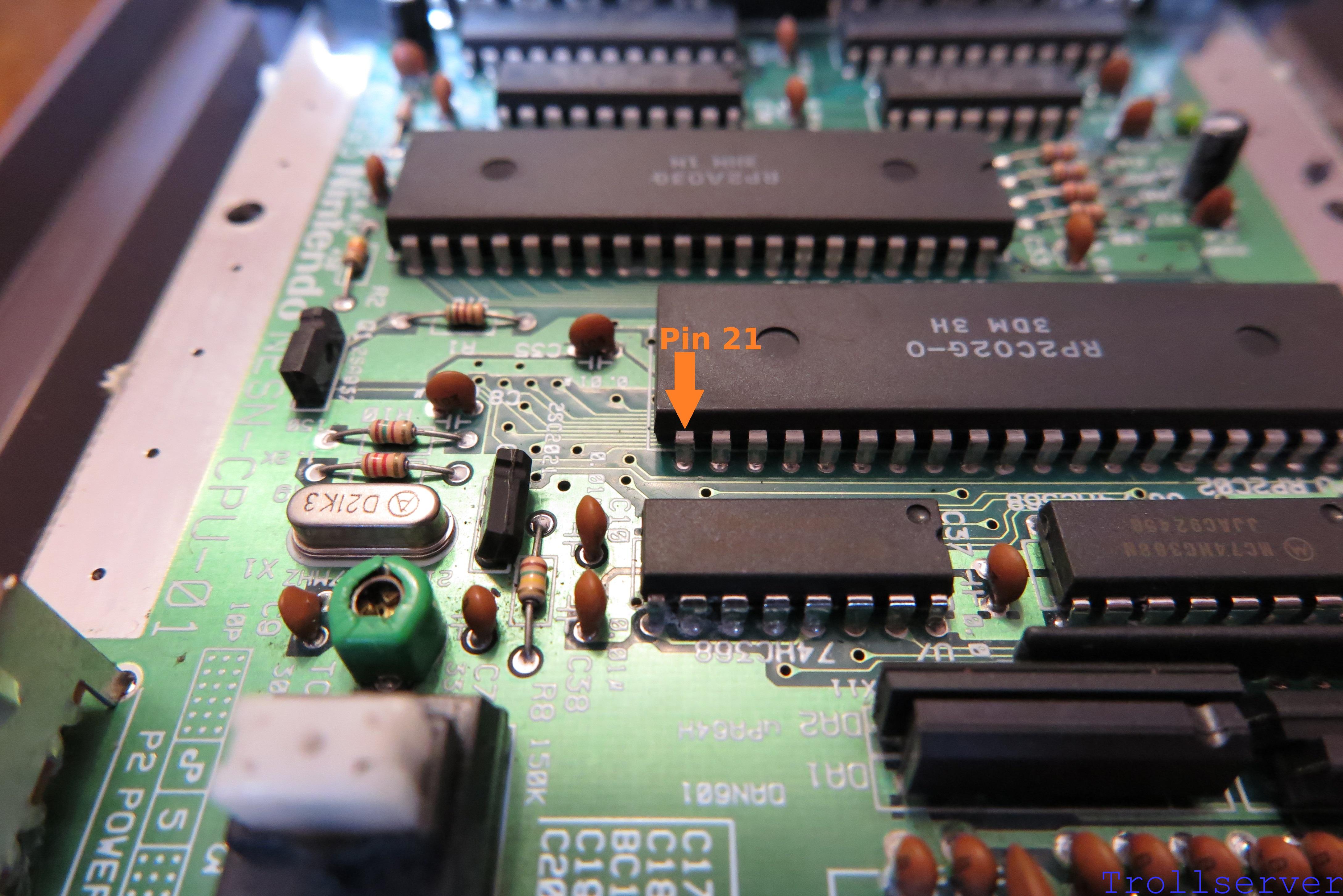
Using something like flush cutters (which can be purchased for cheap on Amazon) you want to cut PPU Pin 21 as close to the motherboard as possible.  The goal is to have as much of the pin still attached to the PPU as you can.

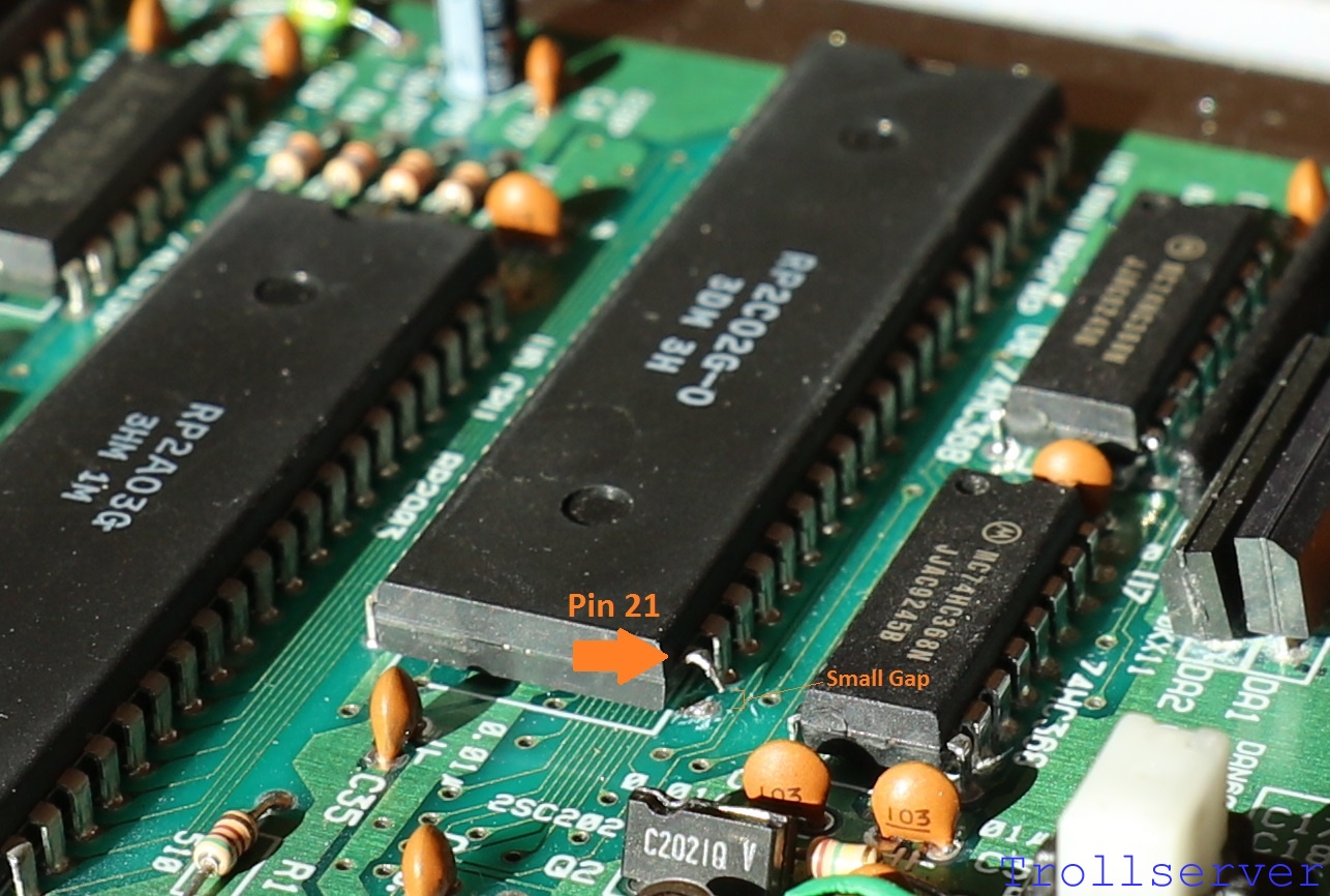
Once you have the pin cut off the motherboard, lift it very gently upward until you can see a small gap of air between the pin and the motherboard.  It’s important that you have completely severed the connection to the motherboard, but it is not important that the pin be far away from the motherboard.  The further you bend it the more likely you are to accidentally break it off of the PPU.  If you break the pin off, you may as well buy another NES Toploader because the one you have is not likely repairable.  Just be gentle and don’t bend it very far and your odds of permanent damage are actually very low.  In fact, I’ve never actually broken one, I’ve just read that it’s possible.

ppu_pin_21

The picture below shows the pin cut and gently bent upward so it doesn’t contact the motherboard anymore.

motherboard_input05


Step 4 – Connect the Video Input Wire

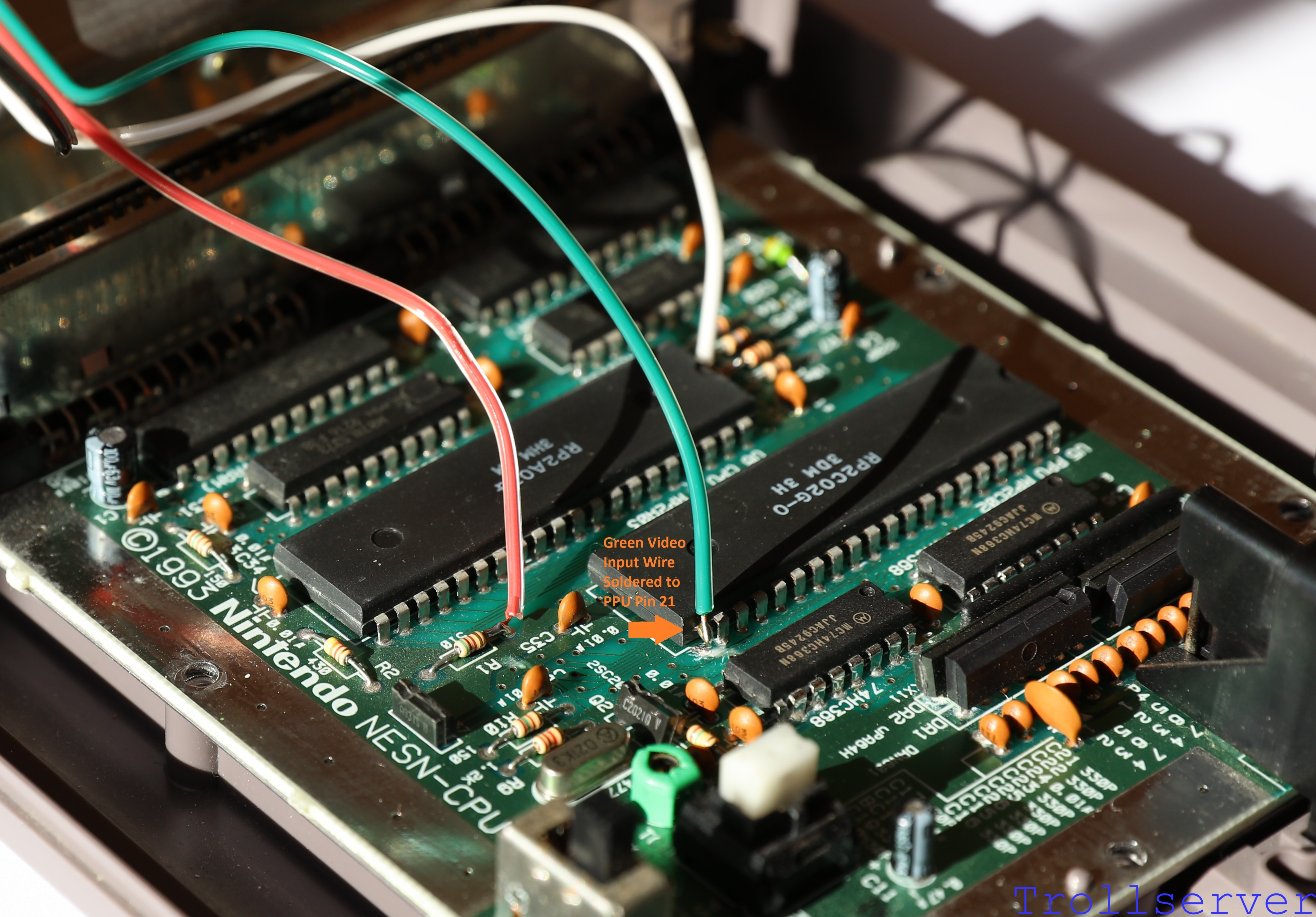
Regardless of whether or not you did the optional Step 3 above, the next step is to solder the green video wire to Pin 21 on the PPU.  Shown here is what it should look like after soldering the Green Video Input Wire to PPU Pin 21.

motherboard_input08


Step 5 – Connect the Ground Wire

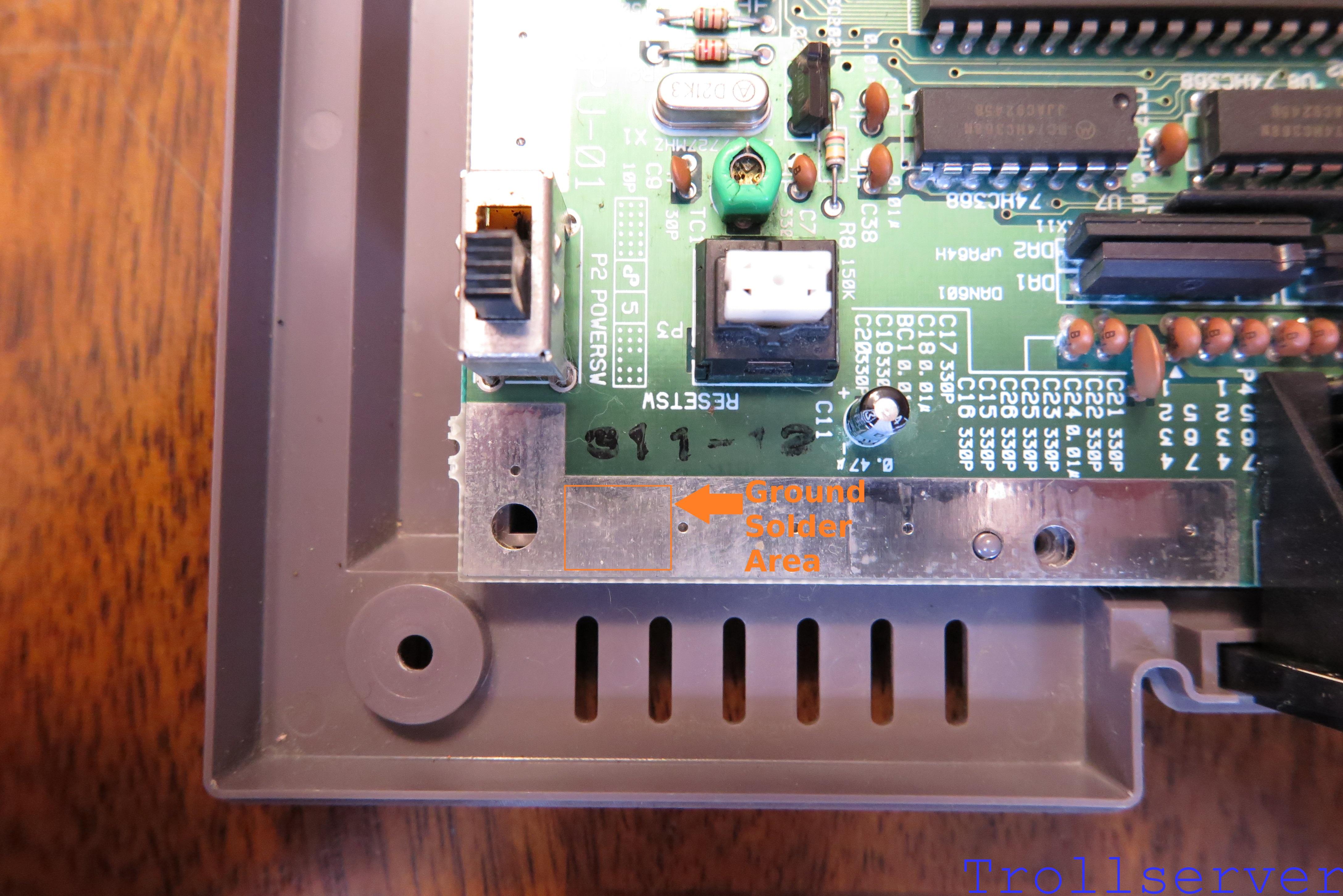
Lastly we need to ground our circuit and to do that we need a connection to ground.  (Funny that.)  The best place I’ve found to do that is the ground band that goes around the whole motherboard.  You can’t solder to that ground band just anywhere though because a lot of it is covered by shielding when you reassemble your NES.  There is an area below the power switch and reset button that does not have shielding covering it and that’s where I make this connection.

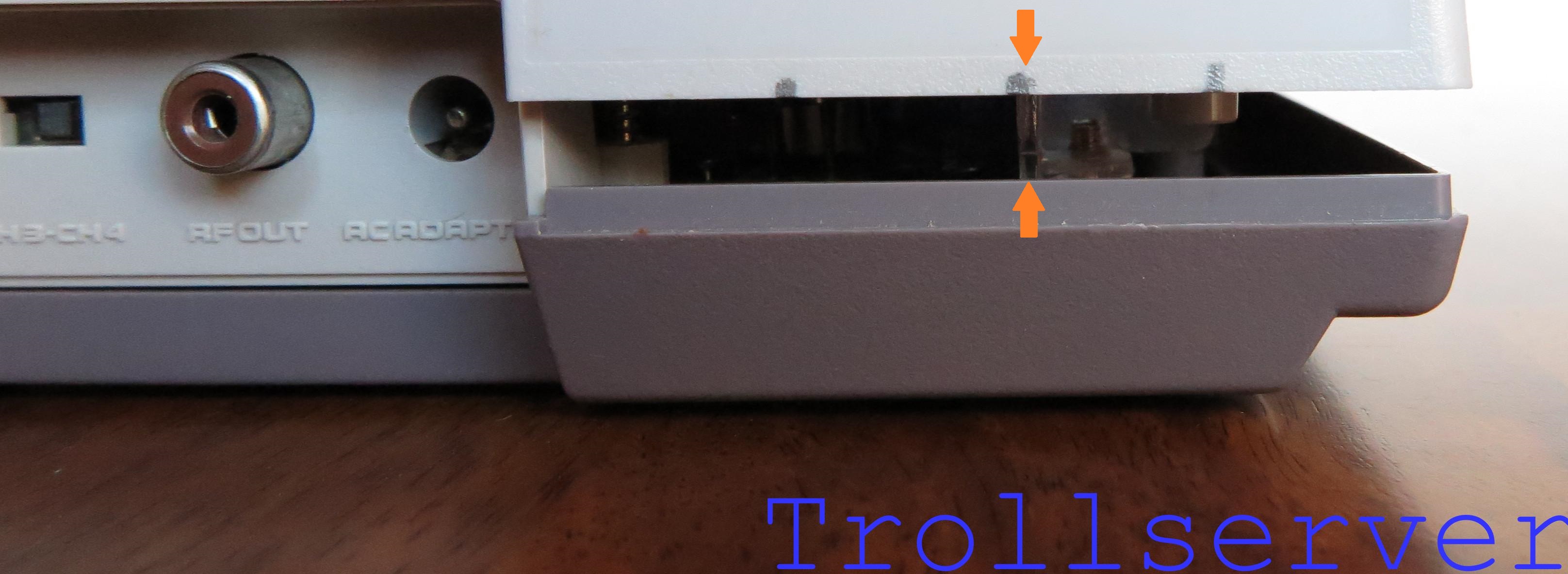
Simply guide the black wire between the power switch and reset button and solder it to the ground band anywhere you like in that area.  I find it best if you center where you solder between the large hole on the left and the little hole to the right.  I’ve highlighted your target area in the image below.

ground_band

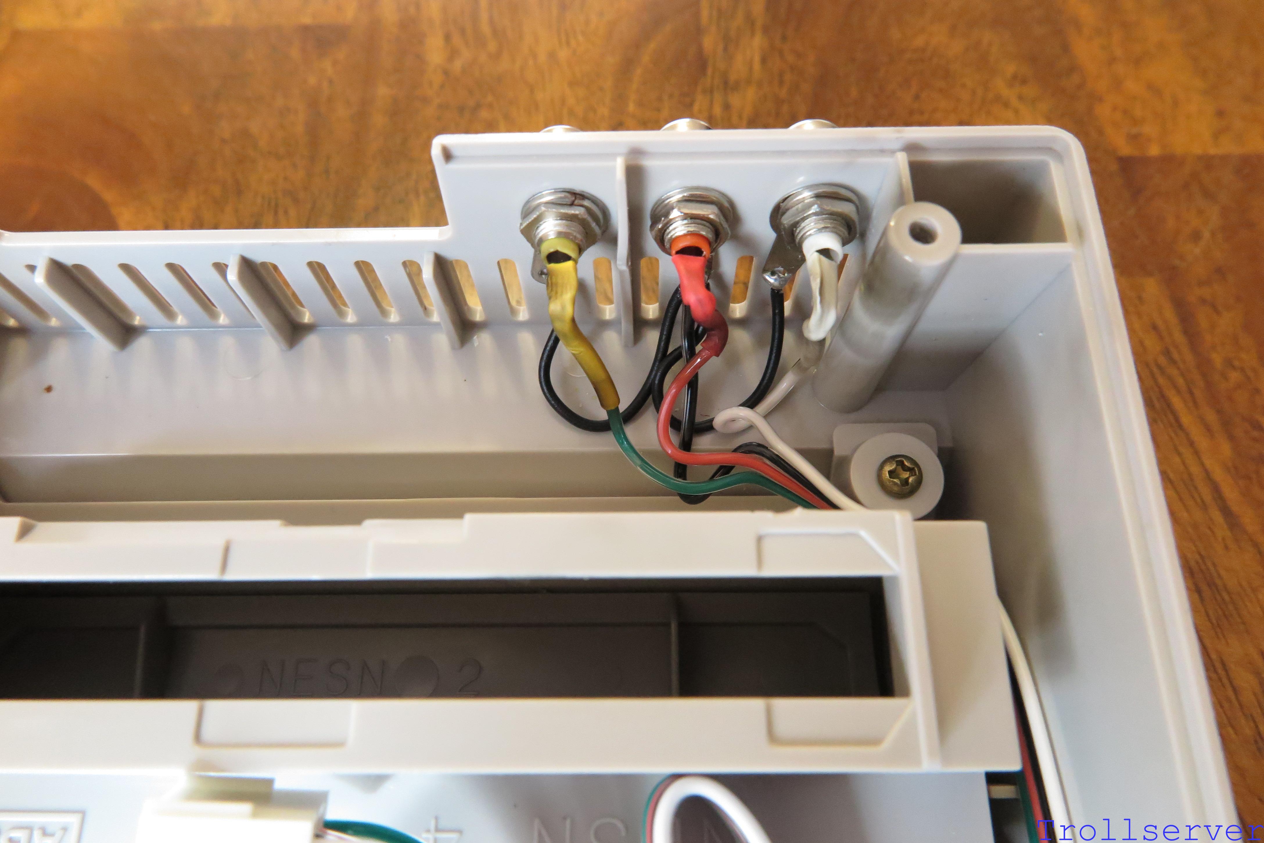
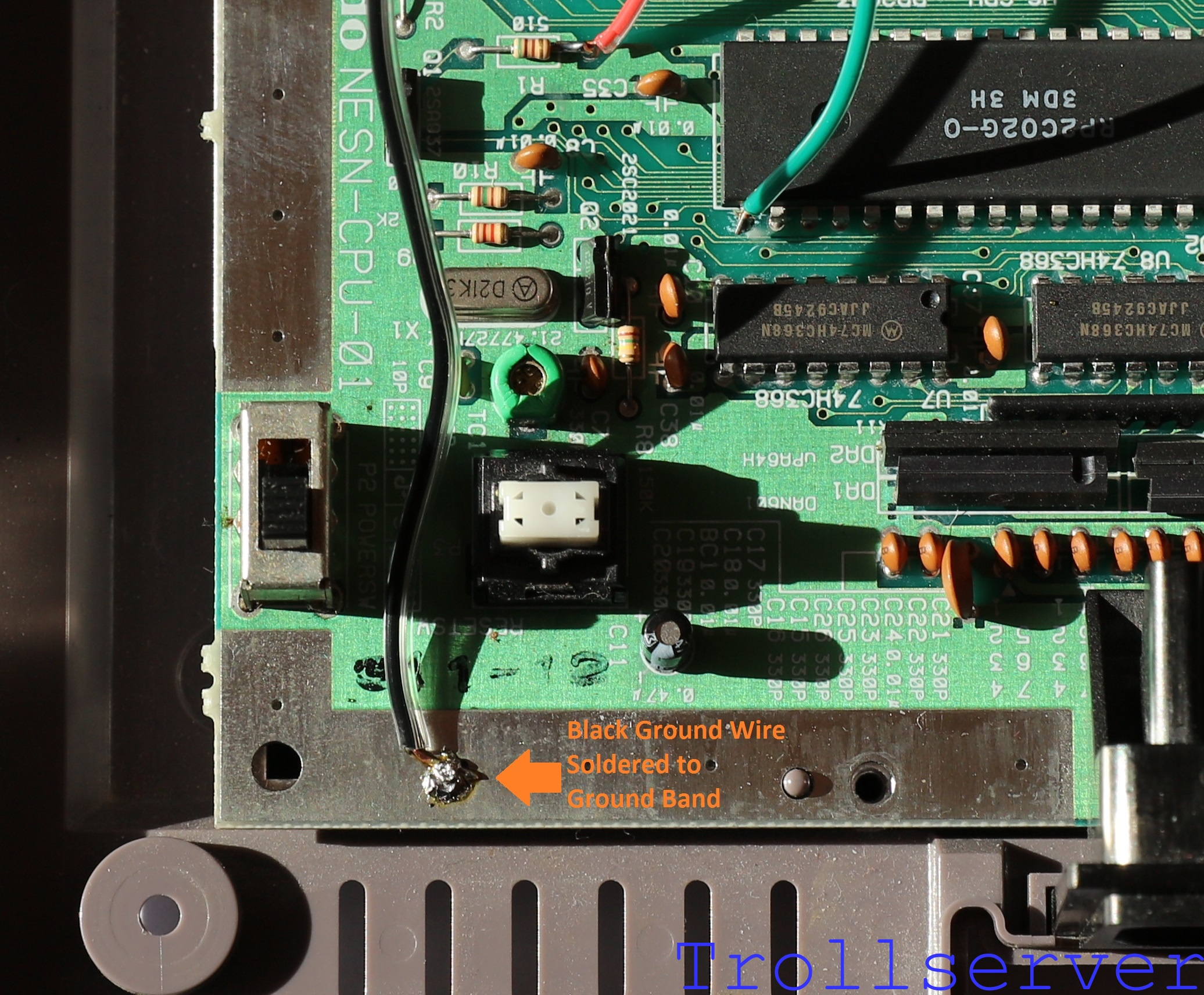
The picture below shows the Black Ground Wire soldered to the ground band.  This is the easiest soldering spot of the whole job, but don’t expect it to look great.  The ground band is very capable of sucking the heat out of your soldering iron so solder doesn’t always flow properly and can lump up like mine did here.  It doesn’t have to be pretty as long as it’s solidly attached.

motherboard_input09


This concludes the soldering of things directly to the NES motherboard.  Next we are going to do a “smoke test.”


To jump between posts in this series, please visit the NES Mod Index.

NES Toploader AV Mod – Motherboard Input – Part 1

To jump between posts in this series, please visit the NES Mod Index.


The first step of connecting to your NES Motherboard in the right places is to make the wire you will use to do it.  This is a lot like the wire you made for connecting the output to the RCA jacks except a bit shorter and simpler.  Start with a 10″ long piece of the 4 conductor wire, a 4-pin connector shell, and 4 connector pins.

motherboard_input01

As you can see in the image above, I separated the wires a short distance for the side that I will use for the connector and a long distance for the side that connects to the motherboard.  To make using this wire a little easier I like to pre-cut each wire so it lines up better with the part of the NES motherboard that it needs to connect to.  Leave the Black wire the full length.  Shorten both the Green and the White wires each by about 1″.  Then shorten the Red wire by about 2″.

The process of building the connector is the same as it was for the output wire, but the other way around.  This is just because the color order of the input wires is the opposite of the color order of the output wires.  Line up the side of the wire that you separated only a short distance with the connector.  Place it so the wires, from top to bottom, are in the order of Green, Red, Black, then White as shown below.

motherboard_input02

Solder and crimp on your connector pins and build the connector after flipping the whole 4 conductor wire over the same way you did for the output connector.

motherboard_input03


Head over to Part 2 to continue.

To jump between posts in this series, please visit the NES Mod Index.

NES Toploader AV Mod – RCA Output – Part 2

To jump between posts in this series, please visit the NES Mod Index.


This is the second part of the instructions for adding the RCA jacks to your NES.  This part involves the physical modification of the NES shell so there are places to put the RCA Jacks.  If you haven’t already created the grounding ring wire you should head back to Part 1 for instructions.

Now, for the first time in this process, it’s time to start actually modifying your NES.  Everything we’ve done up to this point has been steps in the right direction, but has left your precious NES Toploader safe and sound.  That all stops here.  If you are scared about drilling holes, cutting pins on chips that are over 20 years old, soldering directly to the motherboard, just plain decided that vastly superior video output isn’t for you, or are afraid of destroying your NES you should simply stop here and put everything back together.  From here on out the possibility for real damage to your NES is very real.  Having successfully scared the crap out of you, I would like to point out that this is pretty easy and straightforward and if you follow along closely you aren’t especially likely to break things.  🙂

We are going to start by carefully marking the lid of the toploader with a pencil so we can line things up as neatly as possible.  I’ve seen a lot of AV mods where the RCA jacks are all over the place and I’m not a big fan of that.  Perhaps it’s a little bit of OCD, perhaps I just value the final appearance of the NES after this mod more than other people do.  Whatever the reasons, I like it to be neat and I’m going to show you how you can do that.  (Well, to do it as nicely as possible anyway since I’m not doing this with any fancy machines or anything.)

Looking at the back of your NES lid, there is a big rectangle area on the right side below the vents.  Typically it will have a sticker with Mario and a 1-800 number to call for maintenance or service.  I can’t show you what that looks like on my own NES because I peeled it off and threw it away before I decided I wanted to write this guide.  There are several good things about that sticker.  First, you won’t be needing it because it’s an 800 number from over 20 years ago and it probably doesn’t work any more.  Second, you won’t be needing it because what you are about to do would certainly void the warranty that expired on its own over 20 years ago anyway.  Third, the spot they made for it on the back of the NES is a perfect place for 3 RCA jacks.  And last but not least, every time I’ve removed one of those stickers it came off in one neat piece so it’s not even a pain to deal with.

So, uh, peel that sticker off if yours has one.  I’ve placed a orange rectangle to highlight the area where the sticker was.

rca_jacks01

The next step is to make sure we don’t hack through the back in a place that doesn’t have enough room to house an RCA jack.  There are things in the way in there and we need to keep those in mind while we are modifying ours.  There are two plastic structural ribs behind that rectangle.  One is most of the way to the right as you get over by the corner and the other is a little more than 1/2″ from the left of the rectangle.  They’re there to give the back panel more strength and we want to leave them there so it’s good and solid when plugging and unplugging RCA wires.  Using a pencil, mark the spots where they are on the outside of the lid.  I go from the bottom first and then around a little onto the back.rca_jacks02

Next there is one other sneaky thing to avoid.  In the back of almost the entire NES is a large metal heat shield.  The right edge of it is both electrically conductive and in the way.  That’s a bad combo.  To mark it, I put the lid back on the NES and lift the back up just a little until I can see the heat shield.  Using a pencil I mark that too.

rca_jacks03

Now with the things to avoid deftly marked it’s time to determine where to actually do the drilling.  I like to go exactly half way up the rectangle since it looks nice and it puts them far enough from the bottom edge that you don’t have to worry about breaking things.  I eyeball the midpoints between the “things to avoid” marks and use my pencil again to make nice little plus signs where I’ll be drilling.  Please note that perfect spacing here is extremely difficult.  Thanks to plastic and metal things in the way, the typical outcome actually has the right two RCA jacks a little closer to each other than the third one on the left.

rca_jacks04

This is a good time to mention that not all RCA Jacks are created equal.  Even if you order them from the same place I did, they may not actually be the same part as I got.  The quality of the parts is pretty similar, but the only part that is likely to be the same is the jack part.  Minor variances in the screw part in the back or the ground ring or how deep the whole thing goes means that you may have to use a little common sense when putting them in.  I found that a 1/4″ drill bit worked perfectly for me this time, but I’ve used other RCA jacks where I needed to “fine tune” the drill hole a little to be able to get them through the hole.  Just make sure everything fits and doesn’t make electrical connections you don’t mean to make.

Drilling plastic can be tricky.  In general you want to use very little pressure and just let the drill make cute little curls of plastic slowly.  Too much pressure and you can end up with the drill grabbing the plastic and pulling itself into the hole you just drilled.  This generally isn’t really a big deal most of the time, but in this case you may end up damaging the outer plastic of the cartridge slot area since that’s what is right behind where you are drilling.

After a bit of drilling this is what it should look like.  Shown with the RCA jacks that will eventually be in those holes.  Now is also a good time to erase any remaining pencil marks.

rca_jacks05

Now we install the RCA jacks.  To do so, we insert the RCA jacks from the outside of the NES and put on the ground rings we previously wired, then the lock washer (if your RCA jacks had them to begin with), and finally the nut to hold it all in place.  I’m not going to lie, I honestly hate this step more than any of the rest of the whole process.  It’s just a pain in the butt.  Getting all the pieces on there, holding things in place while you tighten things, making sure you put the RCA jacks in the same order as the colors on your wire, dropping things, trying again, etc.  It’s just a frustrating process and I don’t like it.  Without it however I’m afraid we can’t actually get our fancy new signals out of the NES.

The picture below shows how to line everything up inside the NES with the RCA jacks.  The ground rings were wired in such a way that the ground wires start with the middle RCA jack and then go to the outside two RCA jacks.  From the corner, the RCA jacks should be White, Red, then Yellow.  (Actually, the opposite order is just fine too, but try to keep your audio RCA jacks next to each other instead of having the video RCA jack in between them.)  That will make them line up nicely with the White, Red, the Green wires that you will be attaching to them.  It’s pretty tight back there so you want to make sure things are in the right order or you’ll find yourself fighting with where the wires reach the whole time.

rca_jacks13

Note that I have not yet soldered the wires in place.  If you would like to use shrink tubing to keep everything even better protected, now is the time to cut it and put it on the White, Red, and Green Wires.  (If you went ahead and soldered things in place and didn’t put your shrink tubing in place first you are either out of luck or you are starting over on the soldering.)  I like to do use shrink tubing because I feel it keeps the connections a little bit safer from the heat shield in the NES, but it’s definitely not required.  Shrink tubing is the primary reason I split the 4 connector wire a little farther back on this side.  It gives me a nice place to put the shrink tubing while I’m doing the soldering.

rca_jacks14

All that’s left now is to slide the shrink tubing into place and carefully apply a bit of heat to the whole party.  When you’re all done (if you are doing this step) it should look a bit like this.

rca_jacks15

From the outside it should look like this.

rca_jacks16

You might notice that the picture from the outside and the picture from the inside don’t exactly match.  The reason for this was that I messed up the cheap RCA jacks by accidentally breaking the white electrical connection off of the RCA jack.  This is what inspired me to to mention the difference in quality of various RCA jacks on the parts list.  There are several differences between the cheap ones and the good ones.  The barrel of the jack (the part that goes through the NES case plastic) is bigger around, the nut is an actual nut instead of a nut shaped scrap of metal, the center pin solder tab is much shorter (which is a good thing because it helps it to fit properly), and overall it’s got more plastic in it to help hold itself together.  These things actually matter.  So for good measure, here’s a link to where I got my RCA jacks:  Minute Man.


To jump between posts in this series, please visit the NES Mod Index.

1 2 3 4 6