NES Toploader AV Mod – Motherboard Input – Part 2
To jump between posts in this series, please visit the NES Mod Index.
This is the second part of the instructions for connecting your circuit board to the motherboard in your NES. This part involves the scariest bits of the whole process. If you haven’t already created the input wire you should head back to Part 1 for instructions.
One part of this process is optional, but I HIGHLY recommend doing it even if you are scared about it. The difference in output quality is so much better that I can’t really recommend not doing it. I will attempt to make the optional step obvious and to take enough pictures to be helpful but I will be doing the optional step so I won’t be able to provide any pictures of what it looks like if you skipped it.
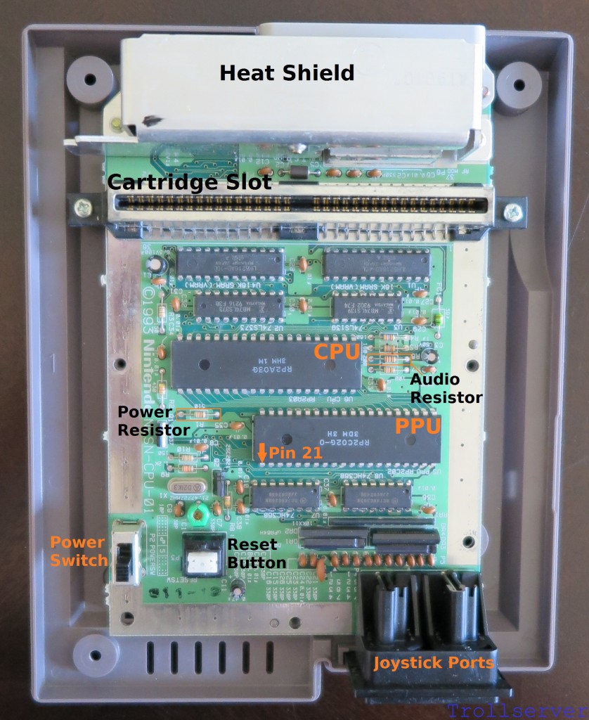
First a little bit of NES motherboard geography. This will make talking about things a little easier later on. To assist with geography there is nothing better than a proper map with convenient labels. I’ve gone with orange or black labels depending on the background color so they stand out nicely. Here is our NES motherboard reference map. (Don’t forget most of the pictures on this site are clickable to see vastly larger versions.)
Step 1 – Connect the Audio Input Wire
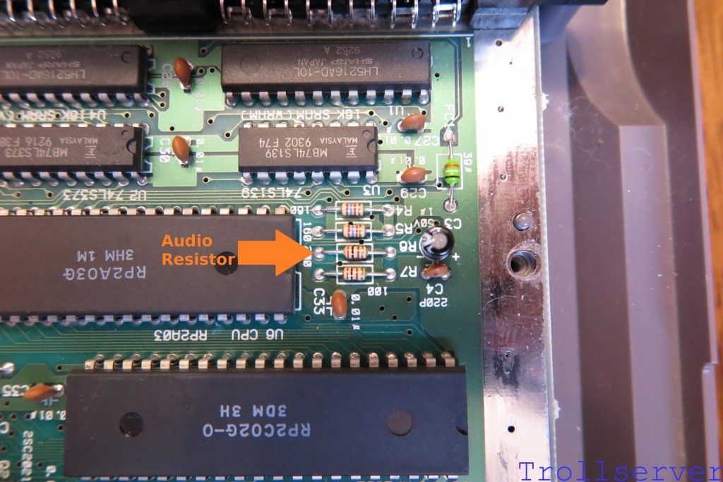
The first thing to wire is the audio. To the right of the CPU is a bank of four resistors labeled R4, R5, R6 and R7. The audio comes out of the CPU and heads through R6. We want the audio directly out of the CPU so we need to solder our white audio wire to the R6 resistor leg that’s on the side toward the CPU (before the signal goes through the resistor).
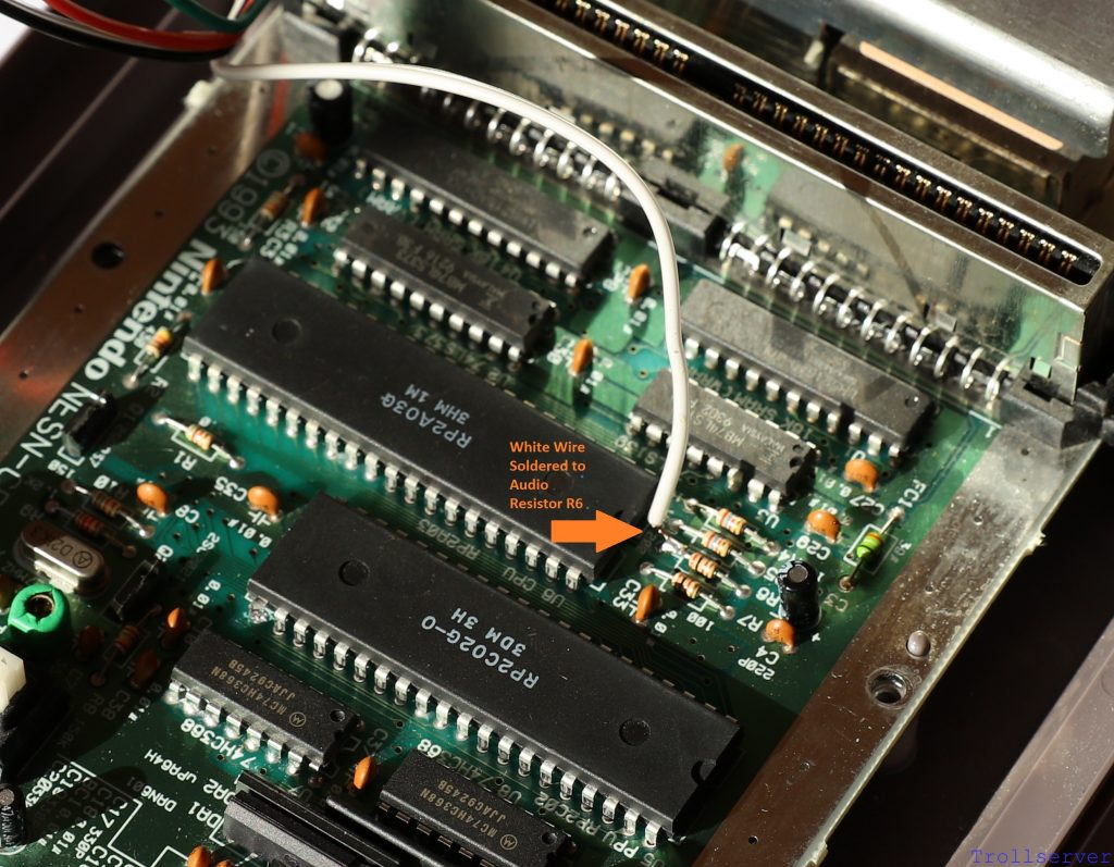
After soldering the White Audio Input Wire to the side of Audio Resistor R6 that is closer to the CPU it should look a bit like this.
Step 2 – Connect the +5V Power Wire
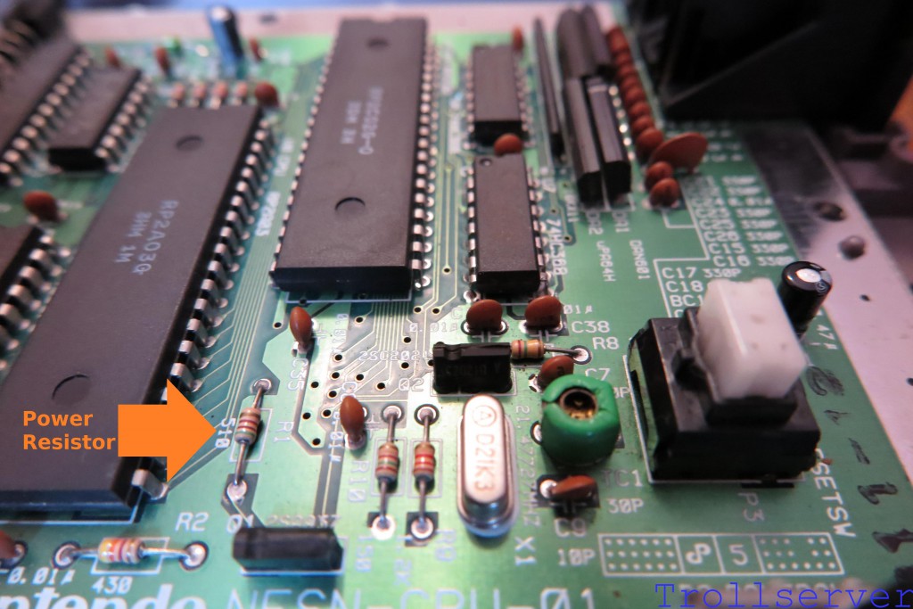
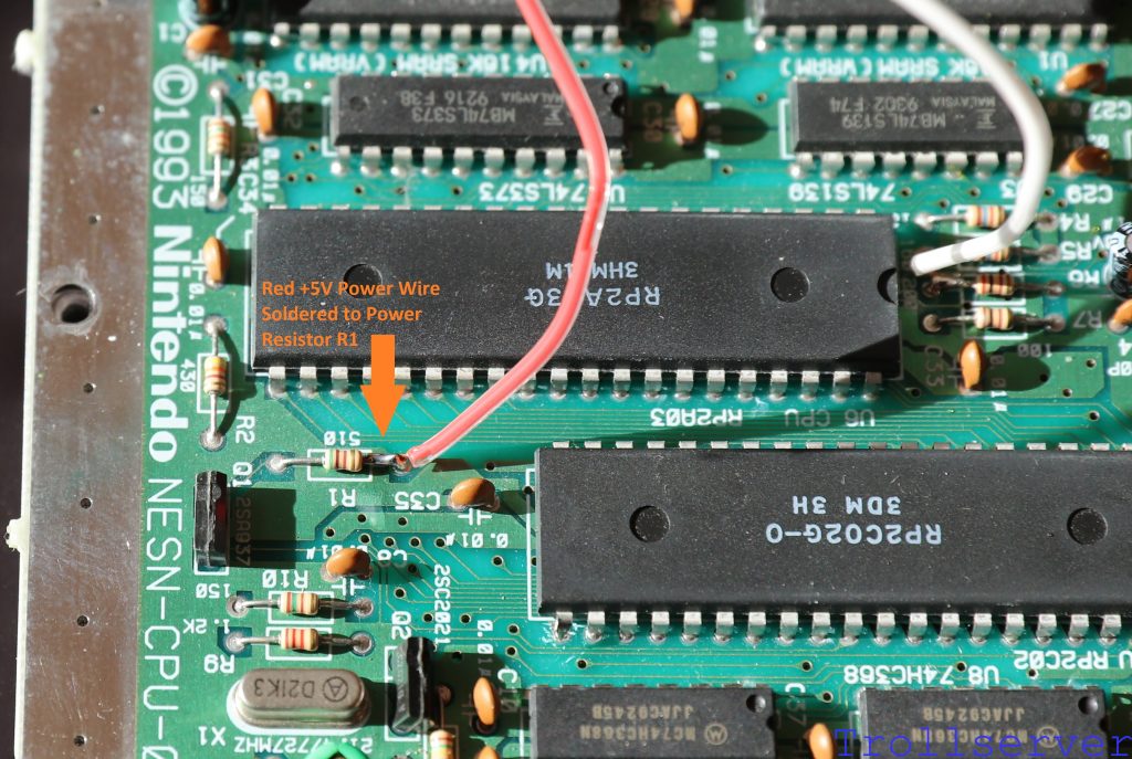
We need some +5V power so we can amplify our video signal before we send it out to the TV. We get that from the resistor on the left side of the CPU labeled R1. In this case we want the power after it has gone through this resistor on its way into the rest of the system. That means we need to solder our red power wire to the R1 resistor leg that’s on the side toward the PPU.
After soldering the Red +5V Power Wire to the side of Power Resistor R1 that is closer to the PPU it should look a bit like this.
Step 3 – Disconnect PPU Pin 21 from the Motherboard
This is the optional step! If cutting and bending the pin of a chip is too scary then skip this step and proceed to step 4 but understand that your video output quality will not be much improved over just using an unmodified toploader.
Pros
|
Cons
|
Ok, now that you have been sufficiently warned about the potential of accidentally destroying your NES and you’ve been given the chance to skip this step, it’s time to plow ahead assuming you are going for it. Let’s do this. 🙂
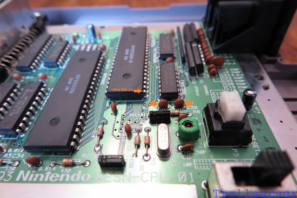
Ok, I lied. One more quick warning here, when cutting the pin be super attentive to the capacitors that are right near where you are working. (Shown with arrows in the image below.) I’ve broken one of them accidentally and it’s a pain to replace. Be especially careful with the capacitor on the left in the picture below. When I broke it I did so by pressing on it accidentally with the handle of the tool I was using to cut the pin. It snapped in half and I didn’t even notice until I was putting things back together, so just be careful.
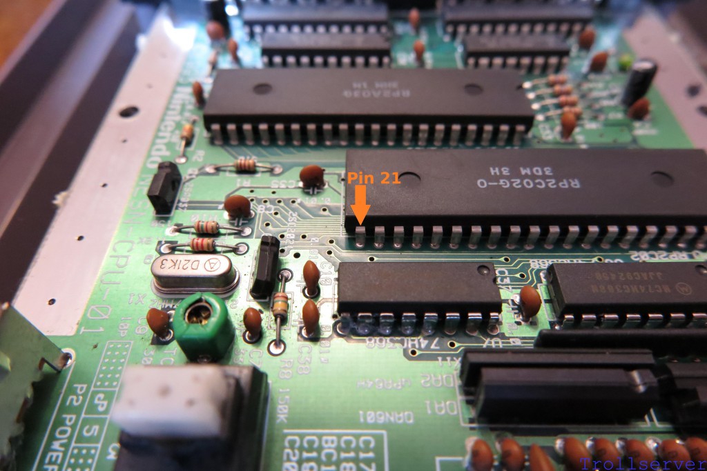
Using something like flush cutters (which can be purchased for cheap on Amazon) you want to cut PPU Pin 21 as close to the motherboard as possible. The goal is to have as much of the pin still attached to the PPU as you can.
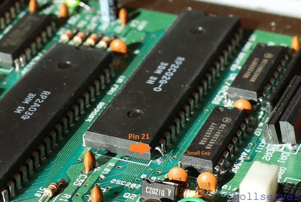
Once you have the pin cut off the motherboard, lift it very gently upward until you can see a small gap of air between the pin and the motherboard. It’s important that you have completely severed the connection to the motherboard, but it is not important that the pin be far away from the motherboard. The further you bend it the more likely you are to accidentally break it off of the PPU. If you break the pin off, you may as well buy another NES Toploader because the one you have is not likely repairable. Just be gentle and don’t bend it very far and your odds of permanent damage are actually very low. In fact, I’ve never actually broken one, I’ve just read that it’s possible.
The picture below shows the pin cut and gently bent upward so it doesn’t contact the motherboard anymore.
Step 4 – Connect the Video Input Wire
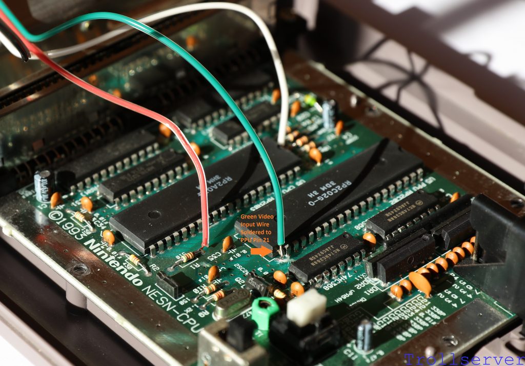
Regardless of whether or not you did the optional Step 3 above, the next step is to solder the green video wire to Pin 21 on the PPU. Shown here is what it should look like after soldering the Green Video Input Wire to PPU Pin 21.
Step 5 – Connect the Ground Wire
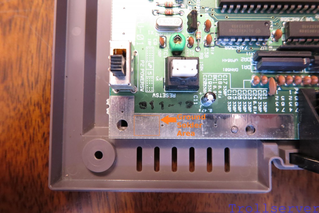
Lastly we need to ground our circuit and to do that we need a connection to ground. (Funny that.) The best place I’ve found to do that is the ground band that goes around the whole motherboard. You can’t solder to that ground band just anywhere though because a lot of it is covered by shielding when you reassemble your NES. There is an area below the power switch and reset button that does not have shielding covering it and that’s where I make this connection.
Simply guide the black wire between the power switch and reset button and solder it to the ground band anywhere you like in that area. I find it best if you center where you solder between the large hole on the left and the little hole to the right. I’ve highlighted your target area in the image below.
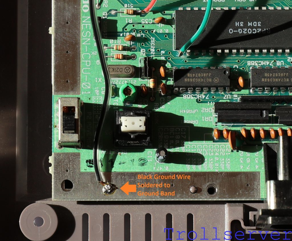
The picture below shows the Black Ground Wire soldered to the ground band. This is the easiest soldering spot of the whole job, but don’t expect it to look great. The ground band is very capable of sucking the heat out of your soldering iron so solder doesn’t always flow properly and can lump up like mine did here. It doesn’t have to be pretty as long as it’s solidly attached.
This concludes the soldering of things directly to the NES motherboard. Next we are going to do a “smoke test.”
To jump between posts in this series, please visit the NES Mod Index.
