NES Toploader AV Mod – Motherboard Input – Part 1
To jump between posts in this series, please visit the NES Mod Index.
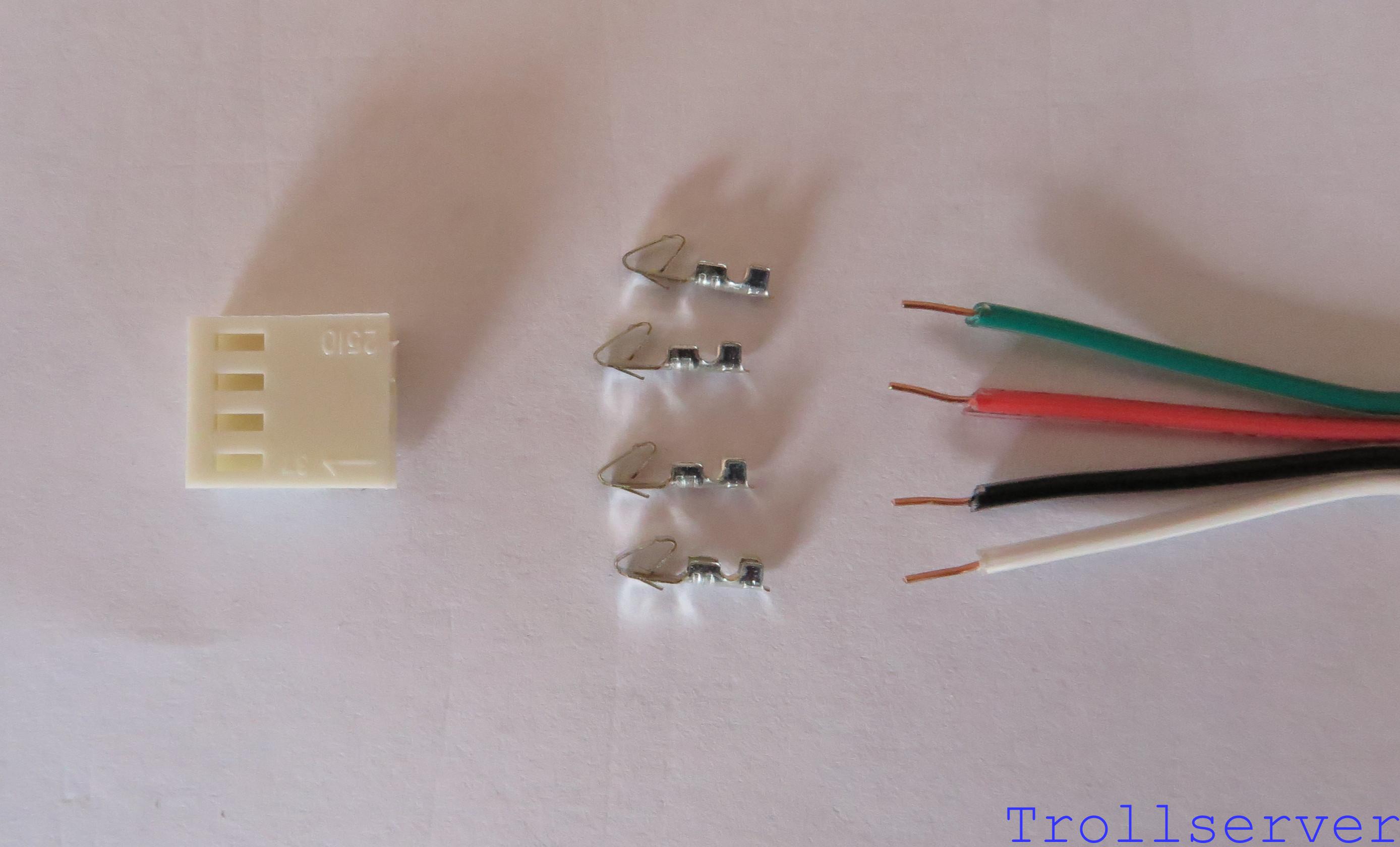
The first step of connecting to your NES Motherboard in the right places is to make the wire you will use to do it. This is a lot like the wire you made for connecting the output to the RCA jacks except a bit shorter and simpler. Start with a 10″ long piece of the 4 conductor wire, a 4-pin connector shell, and 4 connector pins.
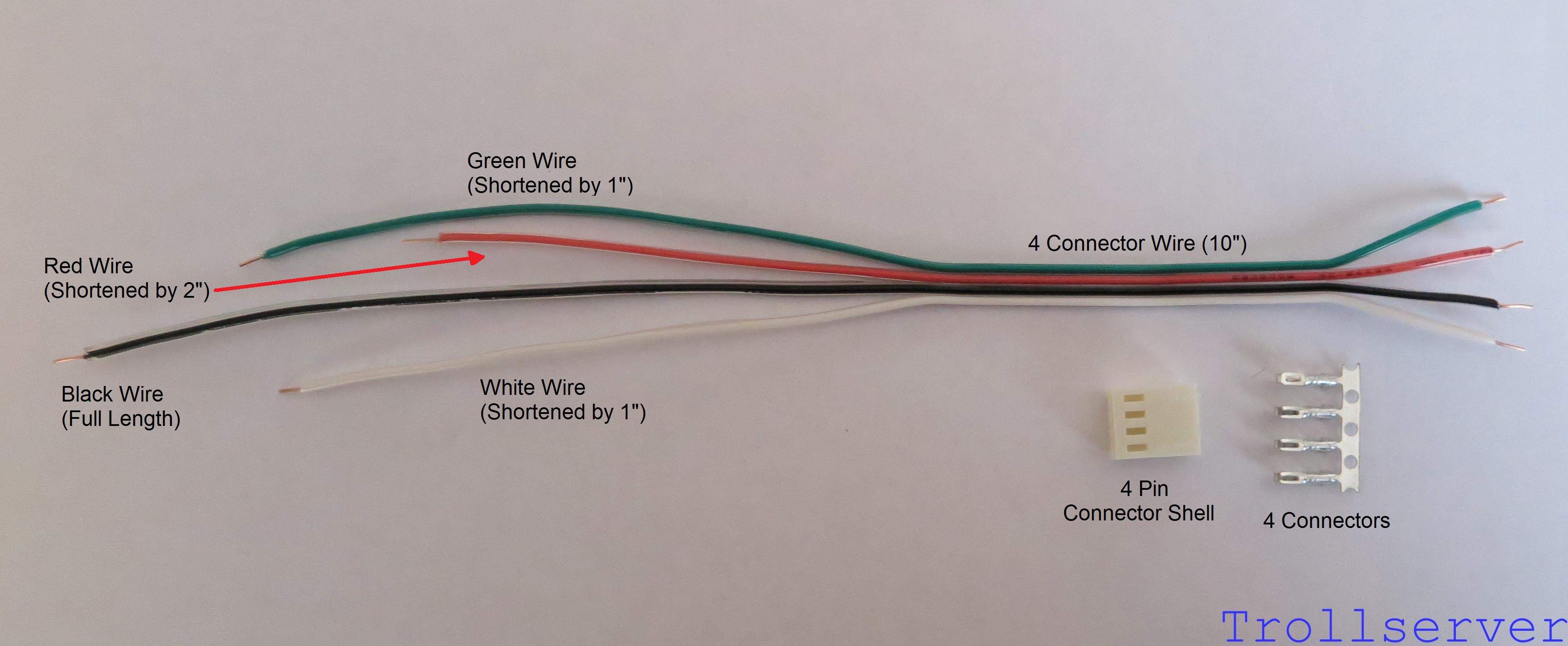
As you can see in the image above, I separated the wires a short distance for the side that I will use for the connector and a long distance for the side that connects to the motherboard. To make using this wire a little easier I like to pre-cut each wire so it lines up better with the part of the NES motherboard that it needs to connect to. Leave the Black wire the full length. Shorten both the Green and the White wires each by about 1″. Then shorten the Red wire by about 2″.
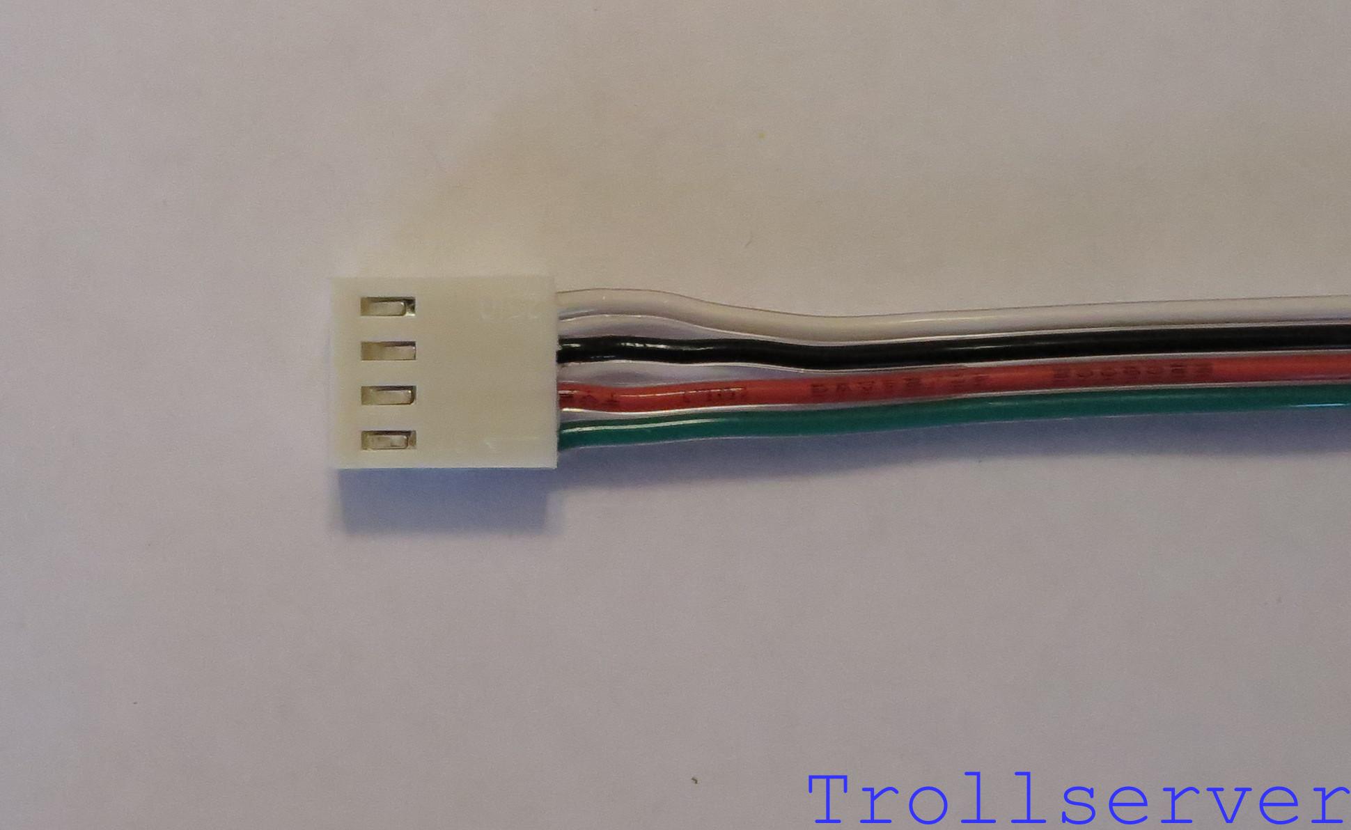
The process of building the connector is the same as it was for the output wire, but the other way around. This is just because the color order of the input wires is the opposite of the color order of the output wires. Line up the side of the wire that you separated only a short distance with the connector. Place it so the wires, from top to bottom, are in the order of Green, Red, Black, then White as shown below.
Solder and crimp on your connector pins and build the connector after flipping the whole 4 conductor wire over the same way you did for the output connector.
Head over to Part 2 to continue.
To jump between posts in this series, please visit the NES Mod Index.