NES Toploader AV Mod – Circuit Design
To jump between posts in this series, please visit the NES Mod Index.
This post can probably be skipped by a lot of people. Electronics nerds such as myself may like to know exactly what they’re building and why. If you are curious or interested in the nerdier bits of this process then you should stick around. If not, continue to the next post about how to actually build this circuit. I won’t judge you. 🙂
For reasons I can’t properly explain, it seems like every AV Mod I’ve ever done has enough power on the audio signal to go right to the TV but the video signal needs to be amplified first.
In an attempt to make every output signal as clean as possible we pass both the audio and video through capacitors as a way of filtering out any rogue direct current (DC) that may have made its way into the signals. The result is potentially cleaner audio and video.
This diagram represents both the audio and the video parts of the circuit together. The circles on the left side of the diagram represent the three RCA jacks that will be on the back of the NES when we are done.
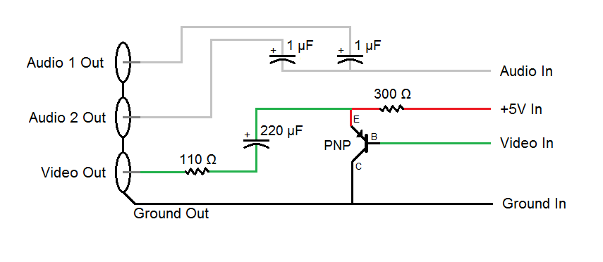
As you can see there, we have a transistor taking in the video signal from the NES and amplifying it with +5V before sending it on its way to the TV but the audio wanders through some capacitors for filtering and heads right out.
To redesign this circuit into a stripboard configuration is relatively straightforward. There are only a few tricky parts to keep in mind. The fact that I’d like to keep my wires color coded so they make sense and the 4-connector wire I like to use has the wires in a specific color order means a couple of constraints on how the input and output work. Specifically, the 4-connector wire is all stuck together in the following color order: White, Black, Red, Green. I like to at least try to use the wires in a way that makes sense with either standard DC current (red is positive and black is negative) or with the standard colors used in RCA jacks for composite audio and video (yellow is video, white and red are audio). Obviously that’s too many colors for 4-connector wire, and we don’t have all the right colors. Here is how I line everything up to make it make as much sense as possible:
Input (top to bottom)
- White = Audio (based on composite standard)
- Black = Ground (based on DC standard)
- Red = +5 Volts (based on DC standard)
- Green = Video (similar to composite standard, but we don’t have yellow so we use green)
Output (top to bottom)
- Green = Video (same color as input)
- Red = Audio (based on composite standard)
- Black = Ground (same color as input)
- White = Audio (based on composite standard)
You’ll notice that the input and output are actually a little different. I don’t mean how I use the 4-connector wire backwards for the output, I mean what things are coming out of the circuit. Specifically we have +5 volts going into the circuit but not coming out. That’s because it is only used for amplifying the video signal and we don’t need it anywhere else.
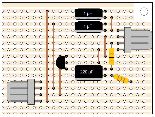
The 4-pin connectors I use to make this circuit nice and modular mean that all 4 inputs or outputs are next to each other on the board. Finally, I prefer not having to cut stripboard conductors if I don’t absolutely have to. All these rules I’ll be following mean that the final board will be slightly larger than it absolutely has to be, some of the components will need to be shifted around a little to make them convenient, and there will be a couple of extra wires on the board to get connections where I need them.
This is what the final design of the stripboard looks like. (Don’t panic, I break down the construction of this circuit board into 3 blog posts with dozens of simple steps to follow.)
Note: If you plan to do an NES Overclock Mod too, I recommend you construct the super compact version of this board. It’s a bit more complicated to build, has completely different input and output wire order, and it throws almost all of the rules mentioned above out the window for the sake of saving a bit of space. The advantage is that in a crowded NES the smaller board helps things fit in better and the compact board is 8 holes tall instead of 16, and 20 holes wide instead of 22. Every little bit counts when things get crowded.
To jump between posts in this series, please visit the NES Mod Index.